HDMI over Twin Cat 5 Wiring Guidance
Before you install a TwinWire system or as part of the troubleshooting process, we recommend reading this infosheet relating to important aspects of the Cat cabling – the digital pipeline for your system.
TwinWire – A different type of transmission than you might think…
TwinWire models use the physcial properties of the copper in the 2x connected Cat 5/6/7 cables to transmit a pure uncompressed HDMI signal at close to 7Gbps. The copper in the cable is being hijacked for a different purpose than intended, this isn’t internet traffic, this is a high frequency HDMI signal. Ideally we want thick copper cores to make signal flow easier and minimum number of pinch points or cable joins on the run (wall plates/patch panels).
Network engineers take note! For our purposes a LAN cable tester is only useful in checking that the cable is wired straight and that all connections are correct. It cannot measure the HDanywhere HDMI data flow because it is not being transmitted as IP data. Traditional methods of testing the network will only give red herring indicators for faults.
The perfect install uses 2 x solid core Cat cables, terminated 568B connected directly between the hub and the receiver without patch panels or wall plates.
General
What is the best type of cable to use?
Currently you can use Cat5e, Cat6, Cat6e, Cat6a, Cat7 or Cat7a with HDanywhere products.
The baseline cable standard for HDanywhere systems is Cat5e. Slightly greater distances can be achieved by using Cat6, or slightly better still with Cat7, which have thicker copper cores for better signal transfer.
Whichever network cable type you choose, ensure that the main wiring architecture is ‘solid core’, not stranded ‘patch’ cabling. Patch cabling can be used for the last few metres of a run (say from a wallplate) but should be avoided over the longer runs as signal transfer over stranded cores is heavily reduced.
The use of pre-made leads is not recommended unless you can be absolutely sure of their construction credentials (i.e. solid core 568B)
Unlike other systems, shielded FTP cable is not a stipulation. If however you preferred this type of cable please ensure compatible shielded accessories are used. Failure to terminate cable screen at all points can induce interference rather than eliminating it.
Patch panels & wall plates
Please be aware that the use of wall outlets and patch panels does cause increased resistance on the cable, introducing ‘pinch points’ for our signal transmission type and will reduce advertised transmission lengths by approximately 10-20% each time.
TIP – instead of using RJ45 wallplates, use brush plates instead to maintain the neat finish. A search for brush plates will yield many results.
Connection termination
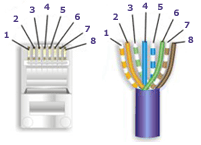
Terminate the cabling using RJ45 connectors to the 568B wiring standard (shown below).

General Troubleshooting Advice
Check that the Cat cable is not bent, knotted, kinked or distorted in any way that would prevent these high frequency signals from traveling throughout the intended length. Also ensure that the cables as far away from potential sources of EMI (Electro-Magnetic Interference ? such as electrical cables, transformers, light fixtures, etc.) as possible. Cables should maintain a 12-inch separation from power cables.
Try re-terminating the RJ45 connectors again, making absolutely sure that every termination is perfect. Ensure that the RJ45 connectors are fully inserted and click locked into place firmly and securely to ensure perfect connector connection
Remember, the perfect install uses 2 x solid core Cat cables connected directly between the hub and the receiver without patch panels or wall plates.
Suggested Installation Do’s and Don’ts
DO maintain the twists of the pairs as close as possible to the point of termination, or no more than 0.5″(one half inch) untwisted.
DO make only gradual bends in the cable where necessary to maintain the minimum bend radius of 4 times the cable diameter or approximately 3cm radius.
DO use low-to-moderate force when pulling cable. The standard calls for a maximum of 25 lbf (pounds of force).
DO use cable pulling lubricant for cable runs that may otherwise require great force to install. (You will be amazed at what a difference the cable lubricant will make)
DO keep Category cables as far away from potential sources of EMI (Electro-Magnetic Interference ? such as electrical cables, transformers, light fixtures, etc.) as possible. Cables should maintain a 12-inch separation from power cables.
DON’T allow the cable to be sharply bent, twisted, or kinked at any time. This can cause permanent damage to the geometry of the cable and cause transmission failures.
DON’T over-tighten cable ties or use plastic ties.
DON’T EVER splice or bridge Category cable at any point 4.
DON’T use excessive force when pulling cable.
DON’T use oil or any other lubricant not specifically designed for Category network cable pulling as they can infiltrate the cable jacket, causing damage to the insulation.
DON’T tie cables to electrical conduits, or lay cables on electrical fixtures
DON’T install cables taught. A good installation should have the cables loose, but never sagging.
DON’T use staples on Category cable that crimp the cable tightly. The common T-18 and T-25 cable staples are not recommended for Category cable. However, the T-59 insulated staple gun is ideal for fastening both Category and fiber optic cabling, as it does not put any excess pressure on the cable.
DON’T use patch cords (cables) or punch down blocks.