This guide explains how to pull data from the Philips API so you can control it directly from uOS, uControl App and uControl Remote.
What this guide will cover:
- How to gather information about your lights and use this to set their states.
- How to create a Philips Hue API so that you can control any light in the property.
- How to add that API into uOS
Important: you must have a developers account first
Before you can access the full Philips Hue API you must have made a Philips Hue Developer account.
Retrieving the IP address
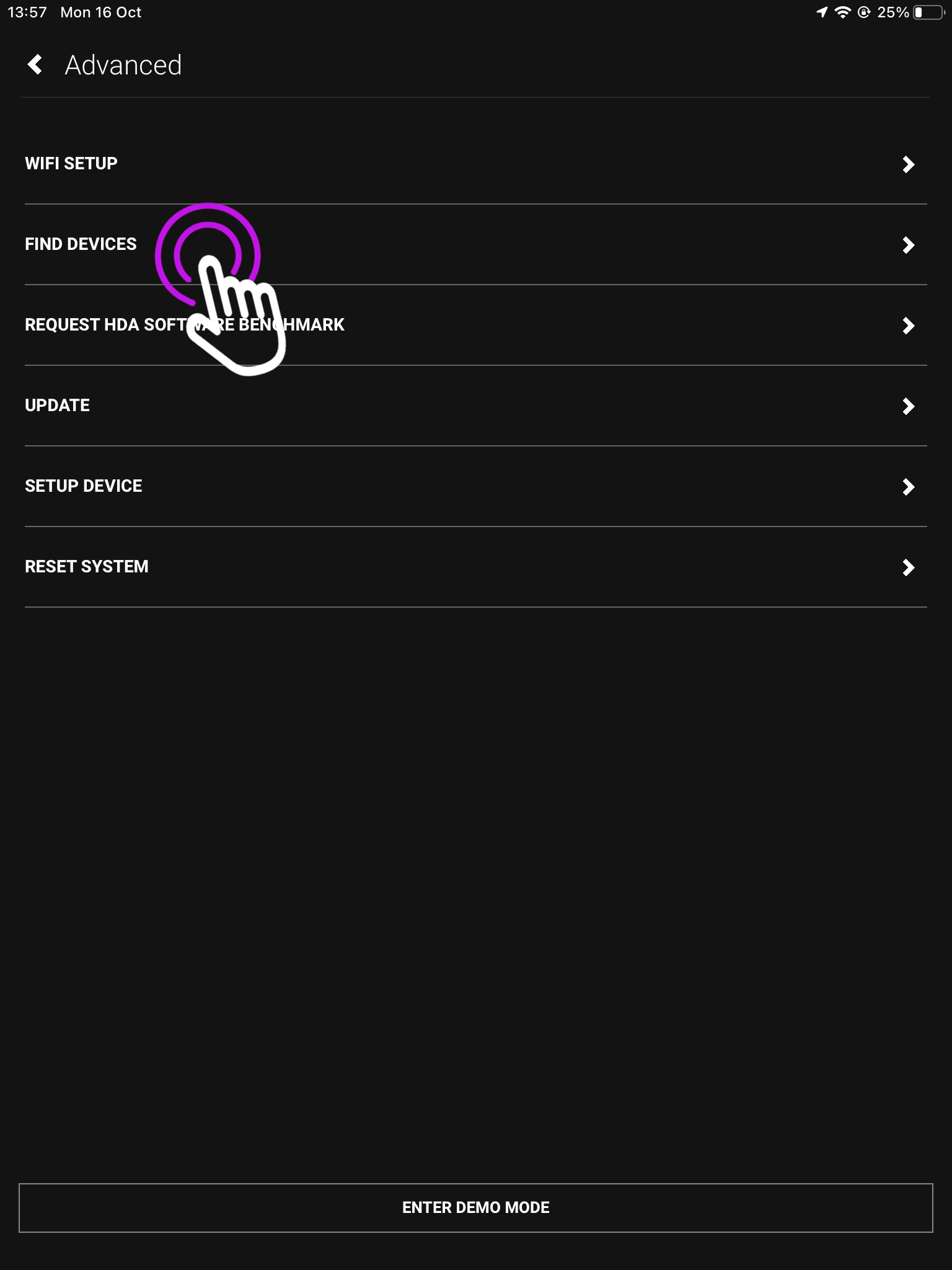
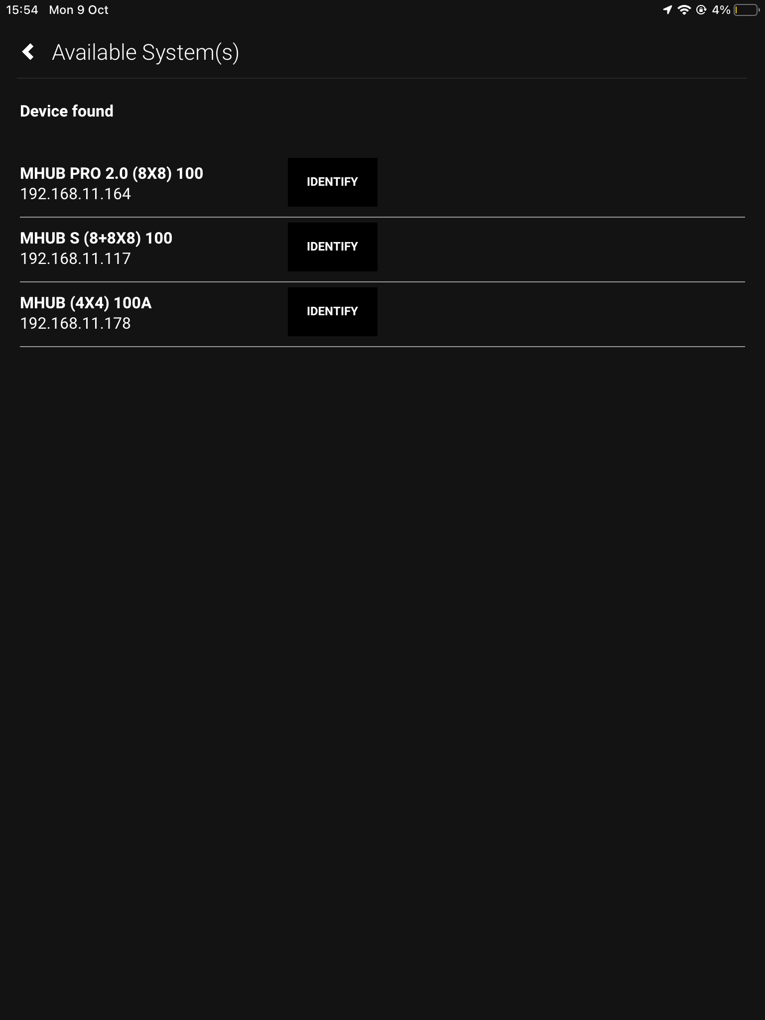
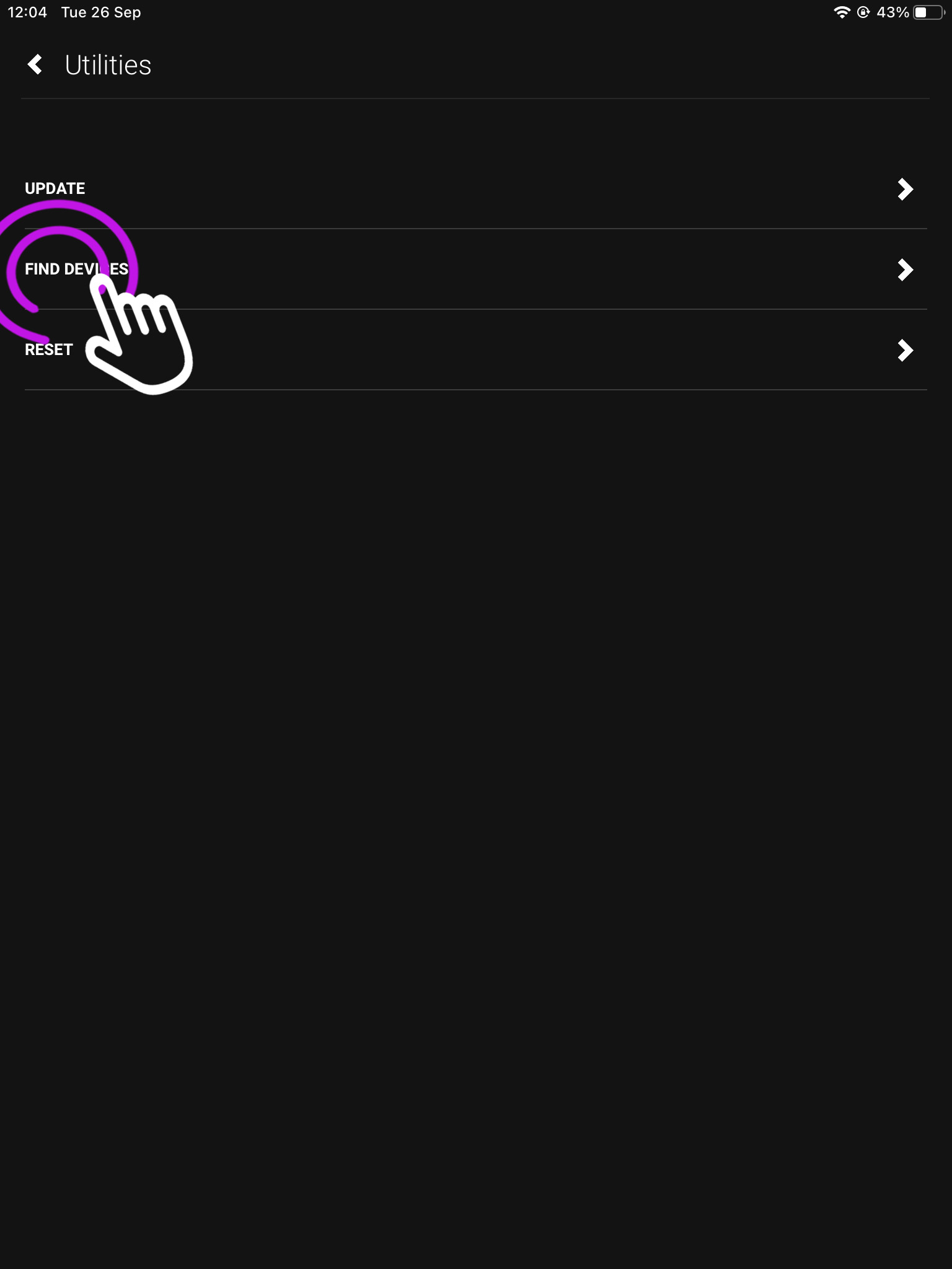
There are a few ways you can get the IP address of your Philips Hue device:
- Use a network scanner app like Fing to find Philips Hue on your network.
- Use Philips Hue broker server discovery process.
- Log into your wireless router and look for Philips Hue in the DHCP table.
- The Philips Hue app – Start the Hue app and push link to connect to the bridge. Use the app to find the bridge and try controlling lights to ensure that everything is working. Then, go to the settings menu in the app, go to Hue Bridges, select your bridge and then the IP address of the bridge will be revealed.
Generating an access token
For the purposes of this guide we are going to pretend that your Philips Hue bridge is on IP address 192.168.1.15 and your uOS device (MHUB, MZMA or Zone Processor) is on 192.168.1.196. We will use this to illustrate all examples moving forward.
Firstly, we need to make an access token so you can make changes to the lighting.
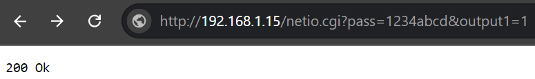
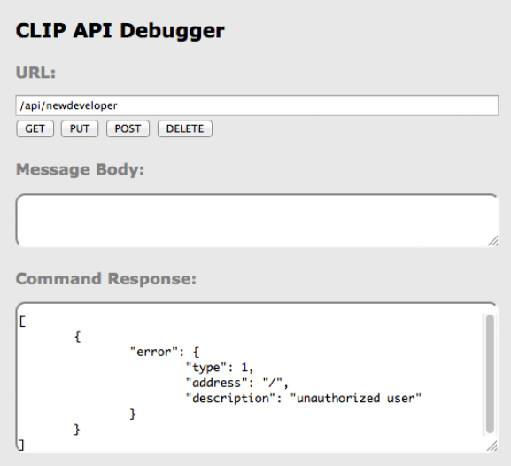
To start this process, head over to the web browser API by typing in the command below with the IP address specific to your Philips Hue bridge.
http://192.168.1.15/debug/clip.html
Once loaded, you should see a grey “CLIP API Debugger” extension pop up, you then need to type /api/newdeveloper and click GET. You will get a reply in the command response which will state you’re an unauthorised user.
We now need to use the randomly generated username that the bridge creates for you. To incorporate this, do the following:
- Start off by typing /api into the URL.
- Then go ahead and type
{"devicetype":"my_hue_app#iphone peter"} into the message body, we have used Peter as our example but your username will most likely be different so change it accordingly.
- Lastly, select your method as POST.
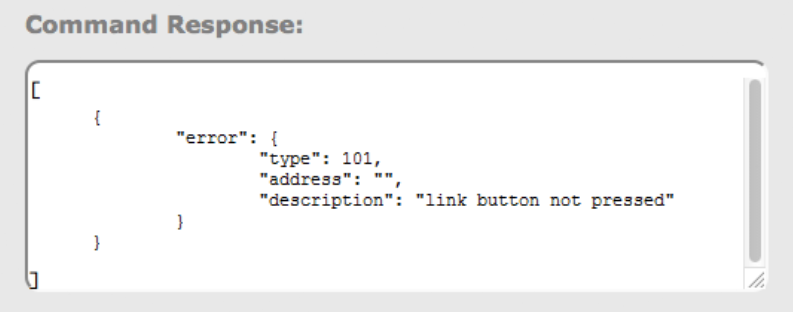
After clicking POST you should get an error response telling you to press the link button, make sure to go press it on the bridge and then click POST again on the API. This is a security step which stops other people from accessing your lights.
You should then be given your access code which will look similar to the one below, make sure you hold onto this as it will be needed for all commands moving forward.
102ad6f46x253e821gcfr9ef1h07j10f
Now we have our acces token and you’re familiar with using the API, we can start controlling our lights. Watch the slideshow to see how to do execute different commands and what they do.
Testing your APIs
As Philips API commands require a command for the URL and also the message body, you will have to test if they’re working on the Clip API Debugger program. If they work, they are ready to be added into uOS!
If it doesn’t work then try the following:
-
Make sure the IP address is correct.
-
Make sure that you do not have any typos.
-
Ensure that your IDs are correct and that you’re observing a light in the correct room and location.
-
Make sure that the structure of the API matches our example no spaces, no special characters, data is in the correct case (often lowercase).
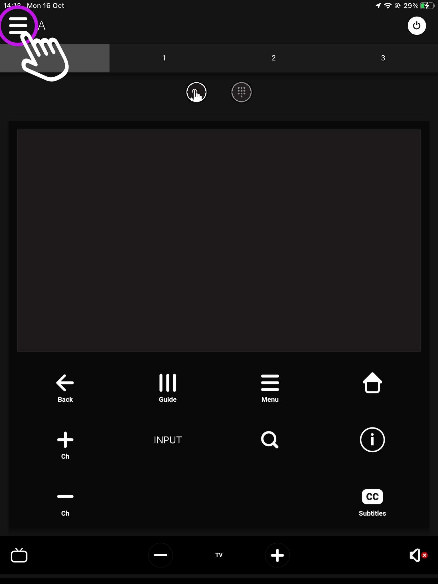
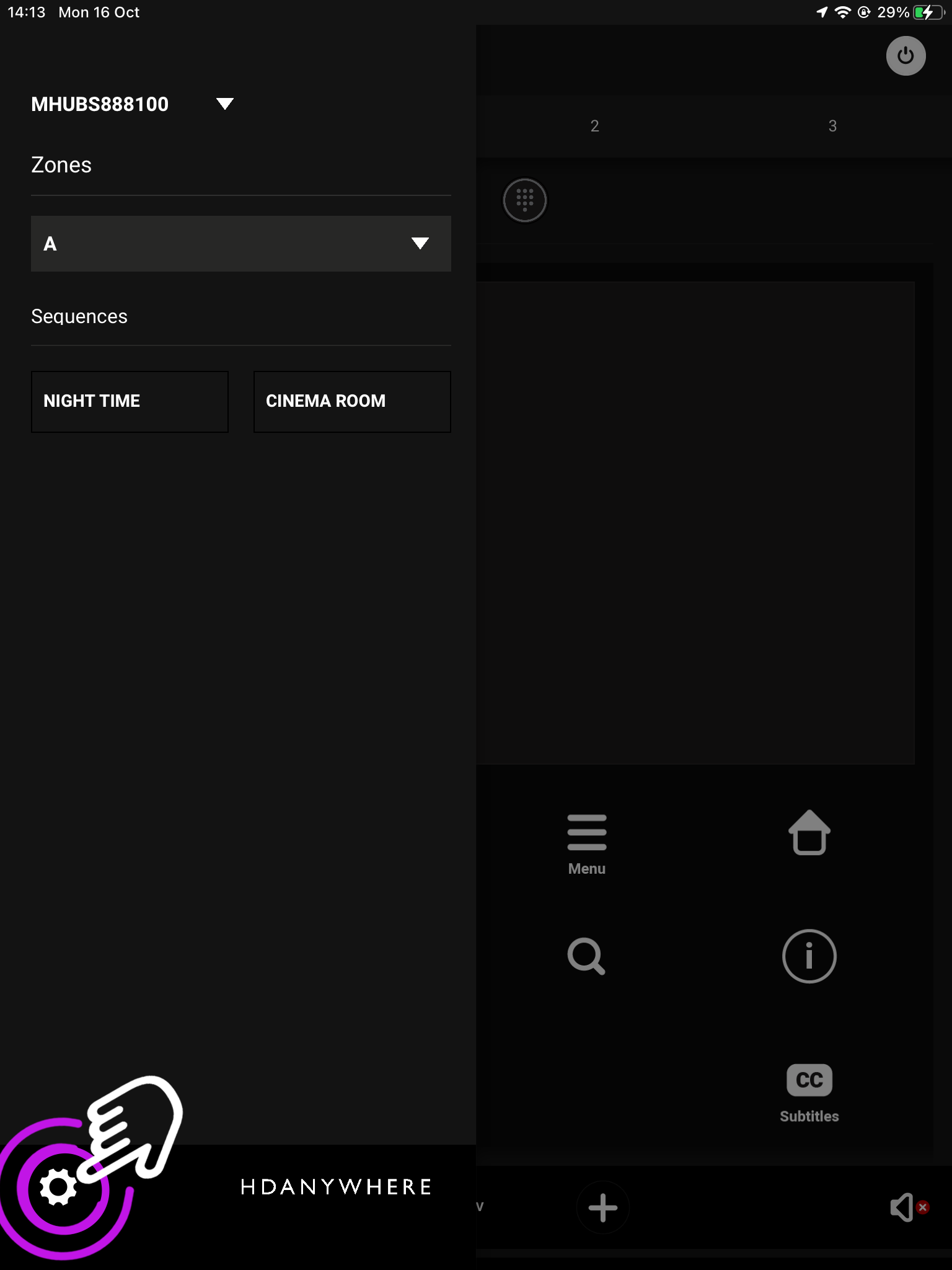
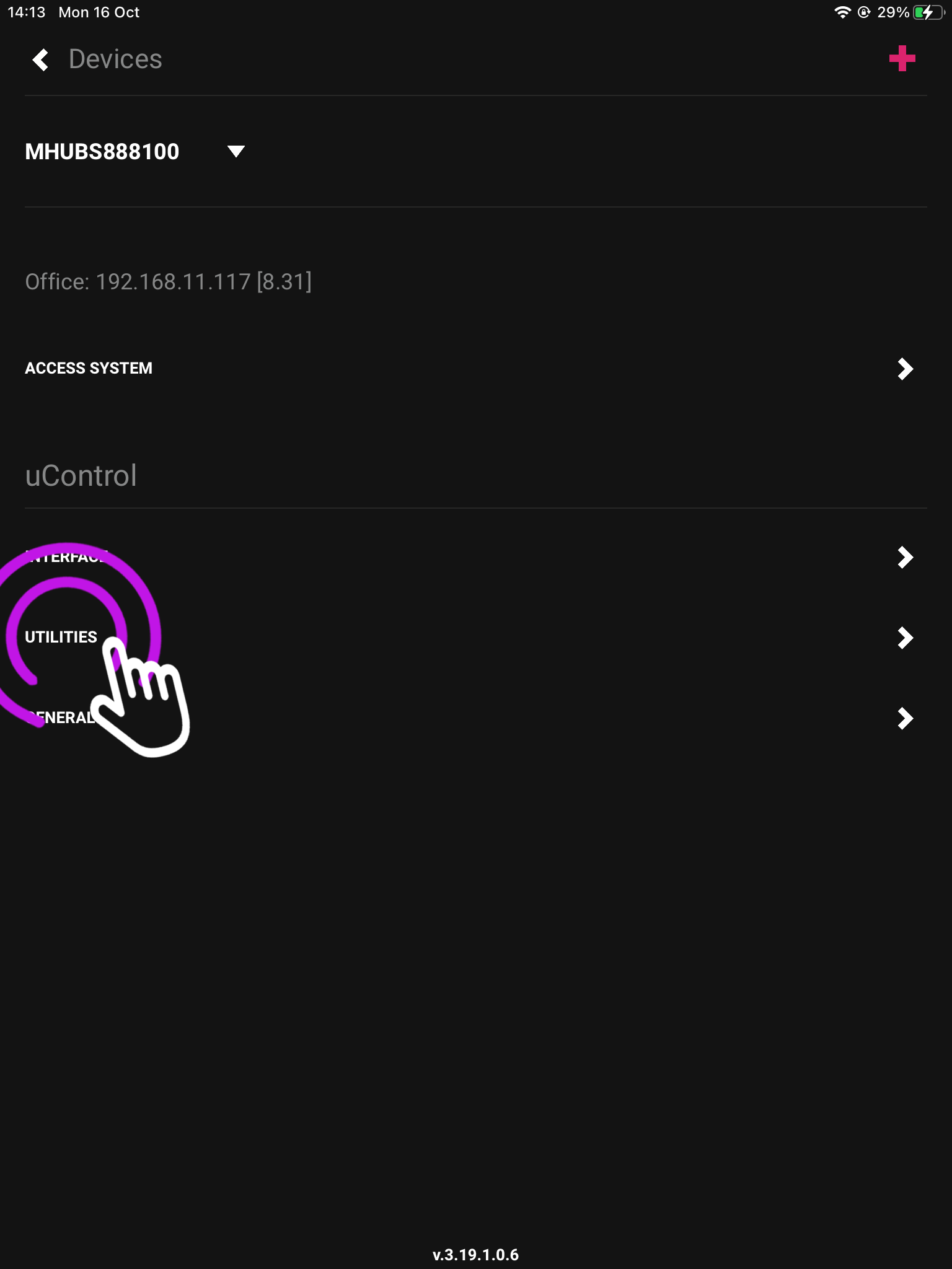
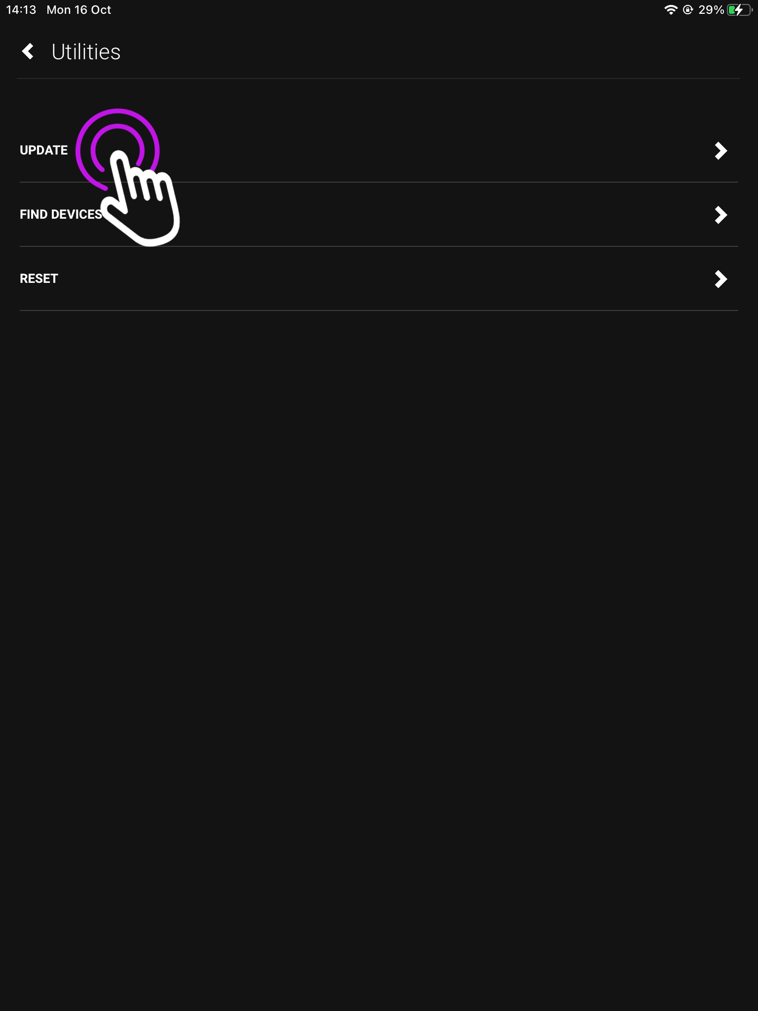
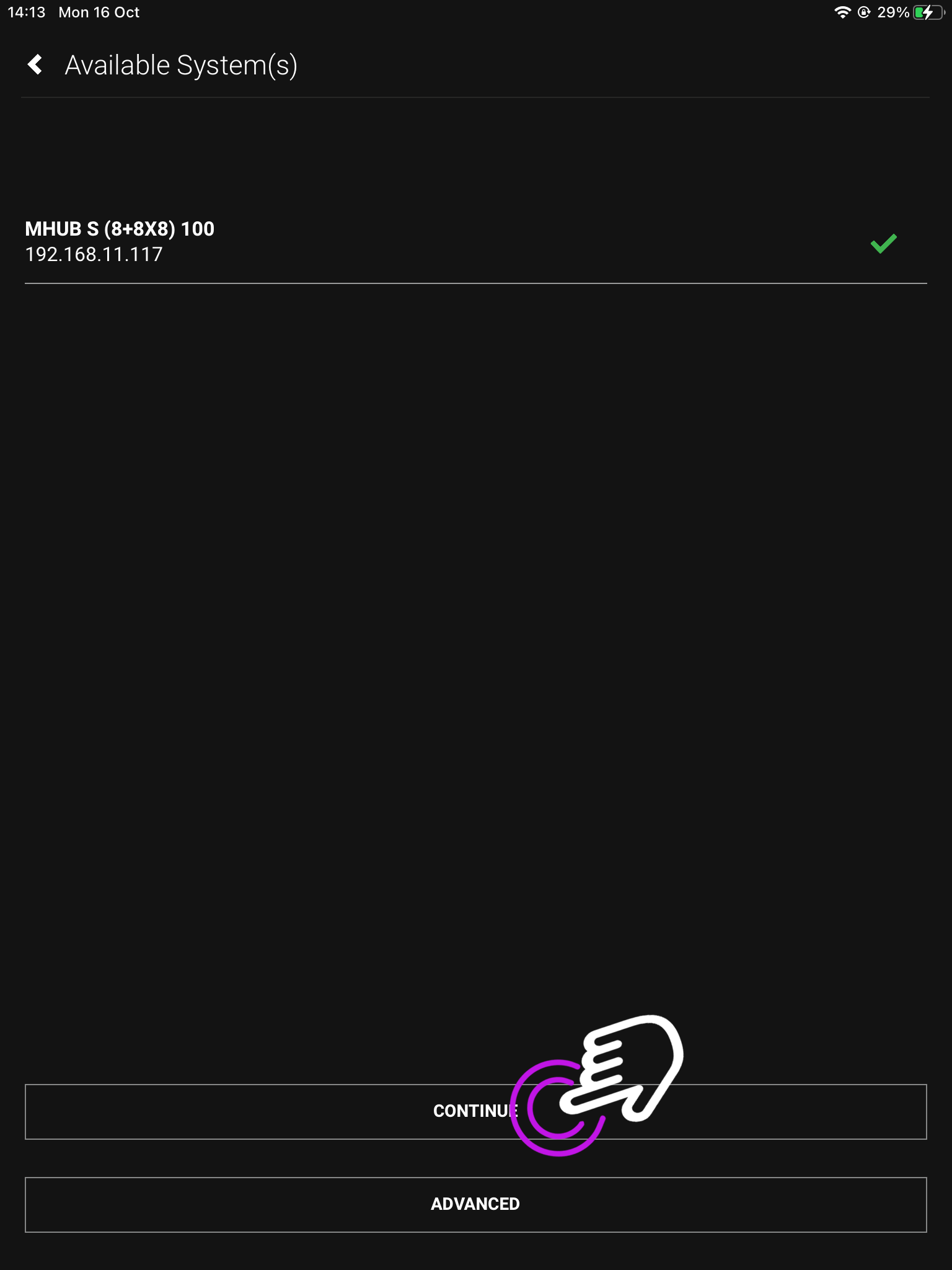
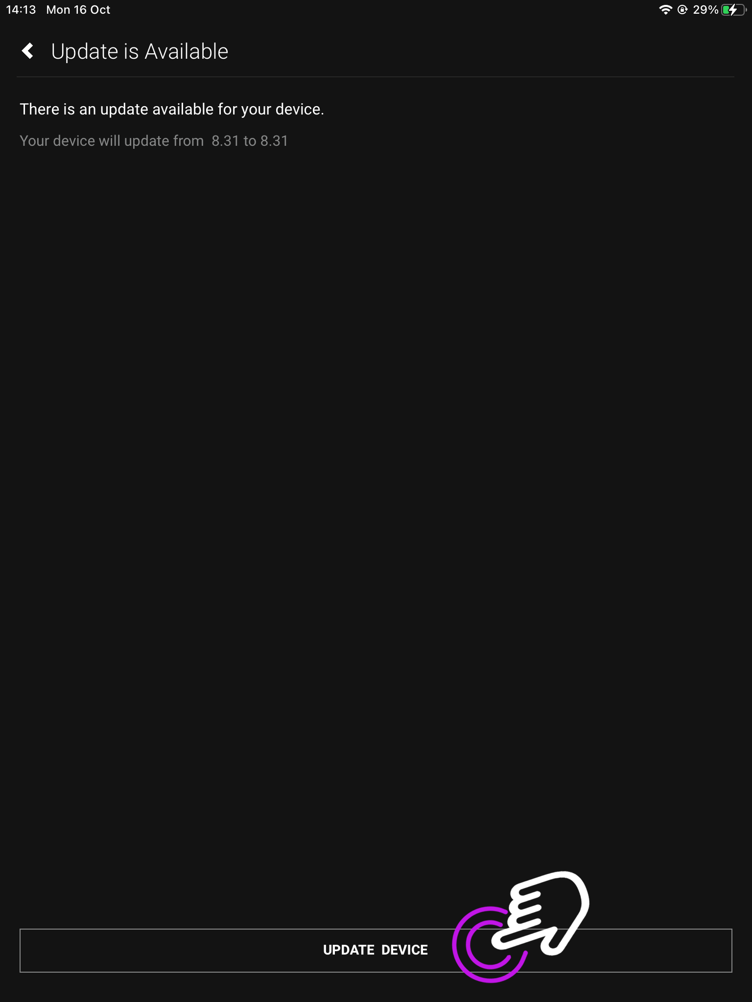
How to add your APIs into uControl
Need more help with the API? Get in touch.
All HDA staff are able to help with any API questions you might have including any advanced features. Get in touch for help or assistance.