Search by Support Category: Miscellaneous
If you want to scan your network for HDA systems but dont have access to an iOS device, you can download the simple tool below.
Windows and Mac versions are included in the download.
To use the Discovery Tool follow these instructions –
- Download and extract the files
- Select the relevent version for your operating system and open the program
- Click on the ‘Scan Network’ button
The Discovery tool will then perform a network scan and will list each HDA device showing its IP address, product code and serial number.
If your download does not start simple right click on the above link and click Save As..
If you want to manually install the Android version of uControl you will need to enable Developer Mode on you phone, and allow app installation from unknown sources.
Once set click the link below.
Important- Development for this version of uControl has stopped, no update will be made, and you install this apk at your own risk.
Philips Hue V2 API
Before you begin, you will need:
- A HTTPS test program such as Postman, available here
- The Philips Hue Bridge address
- A configured Hue lighting system on the same network as the HDA system
- A fully-commissioned HDA or uControl system with the latest version of uOS (MHUB-OS does not support IP integrations) on the same network as the Philips Hue.
- A tablet or laptop using any of the most popular browsers (or an iPhone with the uControl app, at the very least) on the same network as the HDA system.
Please Note – Before you can access the full Philips Hue API you must have made a Philips Hue Developer account.
Step 1:Get data about the Philips Hue system
You need to know:
- Light ID’s
- Group ID’s
- Scene ID’s
There are a few ways you can get the IP address of your Philips Hue device:
- Use a network scanner app like Fing to find Philips Hue on your network.
- Use Philips Hue broker server discovery process.
- Log into your wireless router and look for Philips Hue in the DHCP table.
- The Philips Hue app – Start the Hue app and push link to connect to the bridge. Use the app to find the bridge and try controlling lights to ensure that everything is working. Then, go to the settings menu in the app, go to Hue Bridges, select your bridge and then the IP address of the bridge will be revealed.
Step 2: Build Function
Example Commands
This guide will show you how to trigger events on a Somfy Tahoma system.
Before you begin, you will need:
- A configured Somfy Tahoma hub, with connected devices configured
- The Tahoma hub registered to a user account
- The user account login credentials
- The Tahoma hub pin (located on the bottom of the hub.)
Step 2:Build an IP Connection in uOS
Examples of Somfy commands – Somfy Command Examples
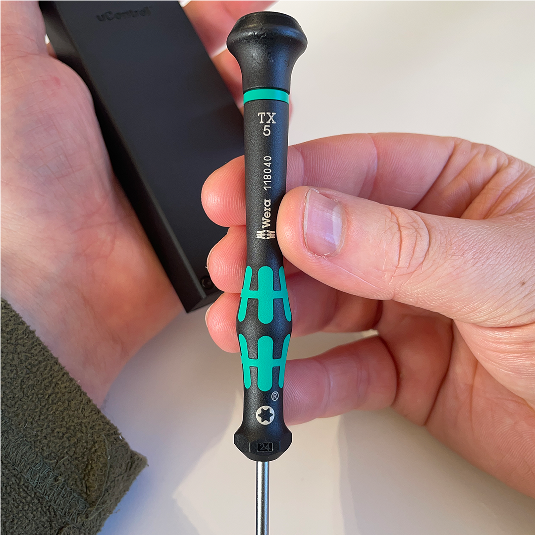
Required tools
uControl Remote will work with any HDA system marked “uControl inside”. These are typically MHUB’s, MZMA or uControl Zone Processors which shipped with uControl OS (uOS) version 10 or above. MHUB’s which were installed with MHUB-OS (MOS) will not support the uControl Remote, but some can be upgraded (see below).
| List of systems that support uControl Remote | ||
|---|---|---|
Natively Supported |
||
| MHUB (4×1+1) 40 | ||
| MHUB (4×4) 100A | ||
| MHUB (6×6) 100A | ||
| MHUB S (8+8×8) 100A | ||
| MHUB S (16+16×16) 100A | ||
| MZMA (6×4) 55 | ||
| uControl Zone Processor 1 | ||
| uControl Zone Processor 5 | ||
| uControl Connect Processor | ||
UpgradableREQUIRES A UCONTROL ZONE PROCESSOR 1 |
||
| MHUB PRO 2.0 (4×4) 40 | ||
| MHUB PRO 2.0 (8×8) 100 | ||
| MHUB U (4×3+1) 40 (coming soon) | ||
| MHUB U (8×6+2) 40 (coming soon) |
Supported Stacked SystemsREQUIRES A UCONTROL ZONE PROCESSOR 1 |
|
| MHUB PRO 2.0 (4×4 & 8×8) & MZMA | ||
| MHUB S (100A) & MZMA | ||
| MHUB S (100) + MHUB S (100A) | ||
IMPORTANT: For the best setup experience, we recommend using a tablet or laptop instead of a smartphone. Using a larger screen makes it easier to navigate the setup process and view all the options clearly.
Pages
THIS GUIDE IS FOR uOS 11 AND ABOVE:
This guide is for HDA devices that are operating uOS 11 or above and have completed the First Boot Process. This guide does not apply to ANY hardware running MHUB-OS or uOS devices that are running on version 11 or lower. How to update your system.
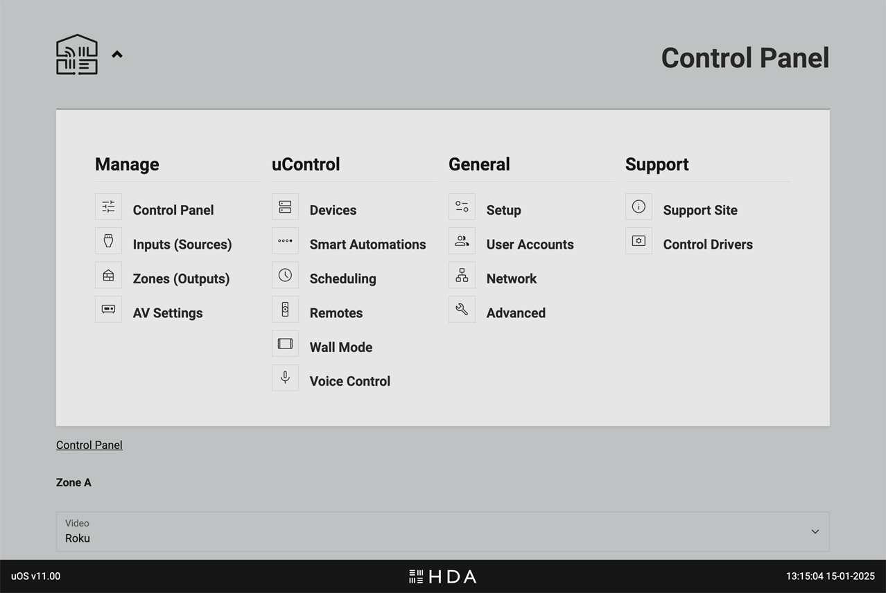
Accessing the menu
The uOS interface features a hidden dropdown menu that provides access to all system settings. To reveal the menu, simply click on the uControl logo located in the top left corner of the screen.
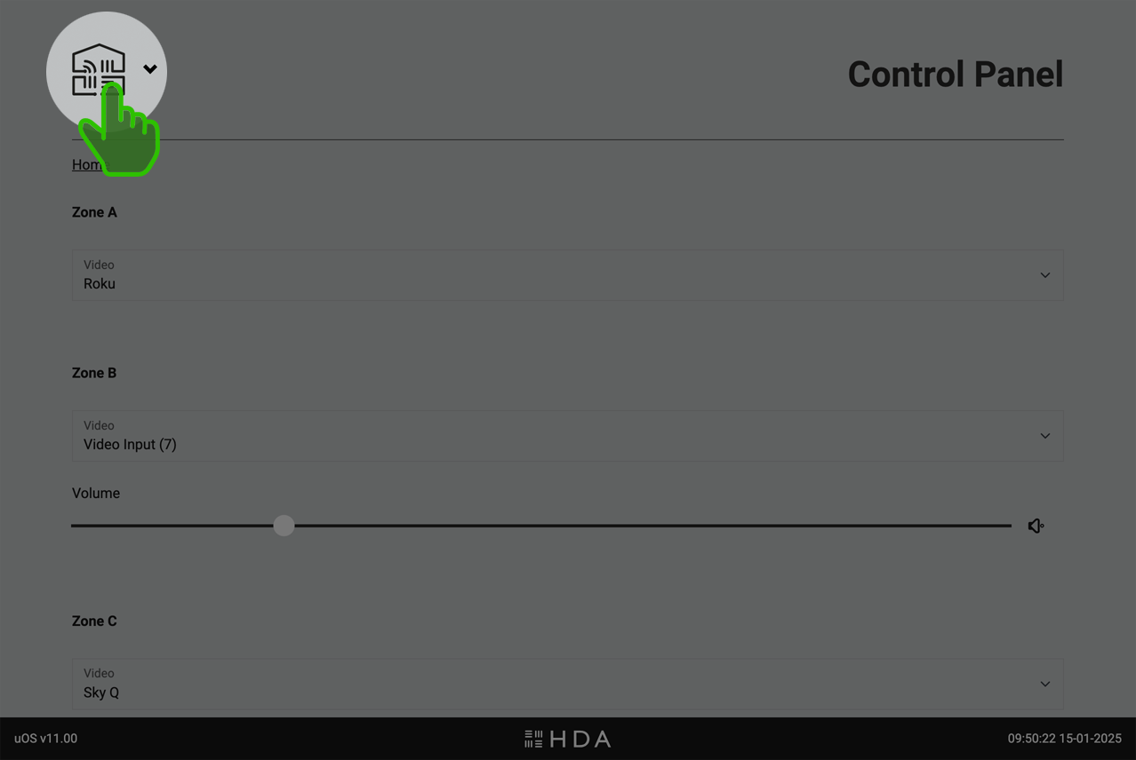
Control Panel
Web Interface for direct control of system state.
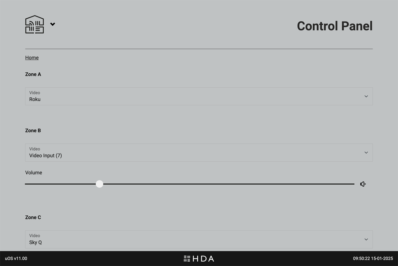
Gives users direct access to the system state via a web interface, bypassing any other control methods. Control is grouped by Zone and will differ depending on what outputs from your HDA device were assigned to them. For example, if you add a video output and an audio output in a Zone named “Living Room” then uOS will display both video switching, audio switching and (hardware dependent) volume controls in the “Living Room” section of the Control Panel
What can you control?
- Source Selection: Choose which video or audio source is routed to the Zone in question.
- Volume: If your HDA device supports volume control then a slider and mute controls will appear.
- System Power: At the bottom of the page is power control for the entire system. It is recommended to use this control only if you wish to turn the entire system off.
What to do if you can not see any controls on this page or controls do not appear to be working correctly.
Ensure that you have created your Zone and assigned either a video or audio output from your HDA device to it. If you are still experiencing a problem, contact HDA Support.
When to use the Control Panel
The web interface is a valuable troubleshooting and backup tool if you have lost control from your normal control method. If you’re experiencing issues with your HDA system, try controlling it directly through this page.
Inputs (Sources)
Management of connected AV input devices.
This page allows you to manage all the AV source devices connected to your HDA system.
- Custom Naming: Give your devices meaningful names (e.g., “Blu-ray Player” instead of “Input 1″) for easy identification throughout the system.
- Global Visibility: Control which input sources are available system-wide. For example, if you have an 8-input system but only use 5 sources, you can disable the unused inputs (6, 7, and 8) so they appear nowhere in uOS. Important: Hiding an input here makes it unavailable across your entire system, unlike Zone-level visibility settings which only control source visibility of active inputs. This is manaaged from the “Zones” page.
- Manage Connections: Tell uOS how multiple HDA devices are connected to one another if you are operating a Stacked System
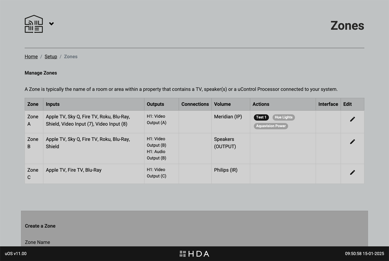
Zones
Manage the Zones in your system.
.
This page is for configuring and customising the Zones within your HDA system. This page provides a clear overview of your entire system from one place.
Key functions on this page
- Zone Naming: Personalise your Zones with names that make sense to you (e.g., “Living Room” instead of “Zone 2″).
- Source Visibility: Control which AV input sources are available in each Zone. For example, you might want to make the “Blu-ray Player” source available in the “Living Room” but not in the “Kitchen.”
- Zone Configuration: Add or remove Zones from your system or change what outputs from your HDA device are assigned to them.
If you are using uControl to control your system, then these Advanced features are also recommended.
- Zone (On/Off) Automation: Select what Sequence is assigned to the Zone ON and Zone Off (e.g. TV off, lights off) event.
- Default Volume Control:Choose which device from your uControl library has primary control over the Zone’s volume.
Recommendation:Add or remove Zones from your system or change what outputs from your HDA device are assigned to them.
AV Settings
Fine-tune your audio and video settings.
.
This page allows you to customise advanced audio and video settings for your HDA system to achieve optimal performance. This page displays settings specific to your HDA device hardware. If you have a stacked system with multiple HDA devices, you’ll find settings for each device grouped by hardware name and type. This allows for granular control over each device in your system.
Key functions on this page
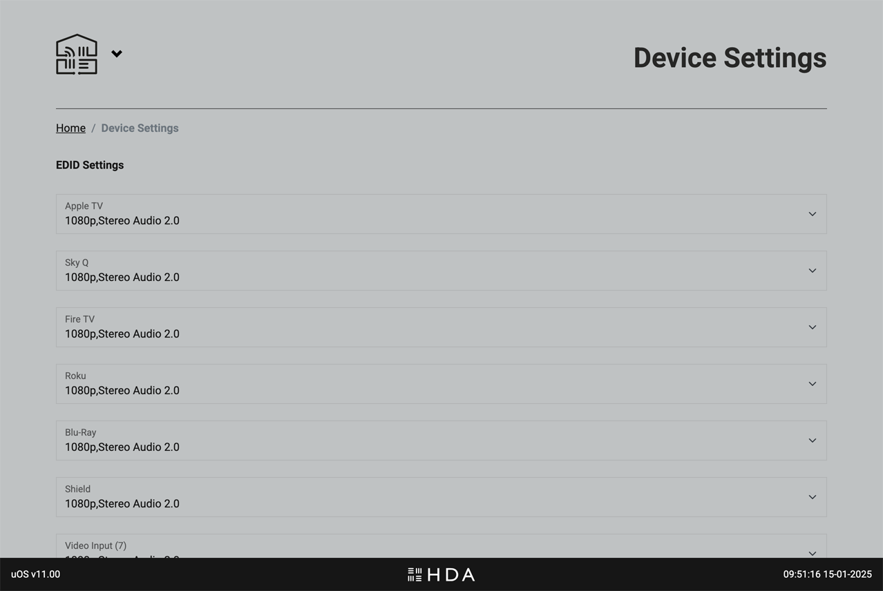
- EDID Management: Control how your HDA device communicates with displays to ensure compatibility and optimal resolution.
- Video Scaling: Adjust how video content is scaled and displayed on your screens.
- Audio Volume Presets:Configure input gain and max volume levels for sources and Zones.
- EQ Settings:Fine-tune audio equalisation for specific Zones or outputs.
Devices
Add new devices to uControl or manage how they work.
.
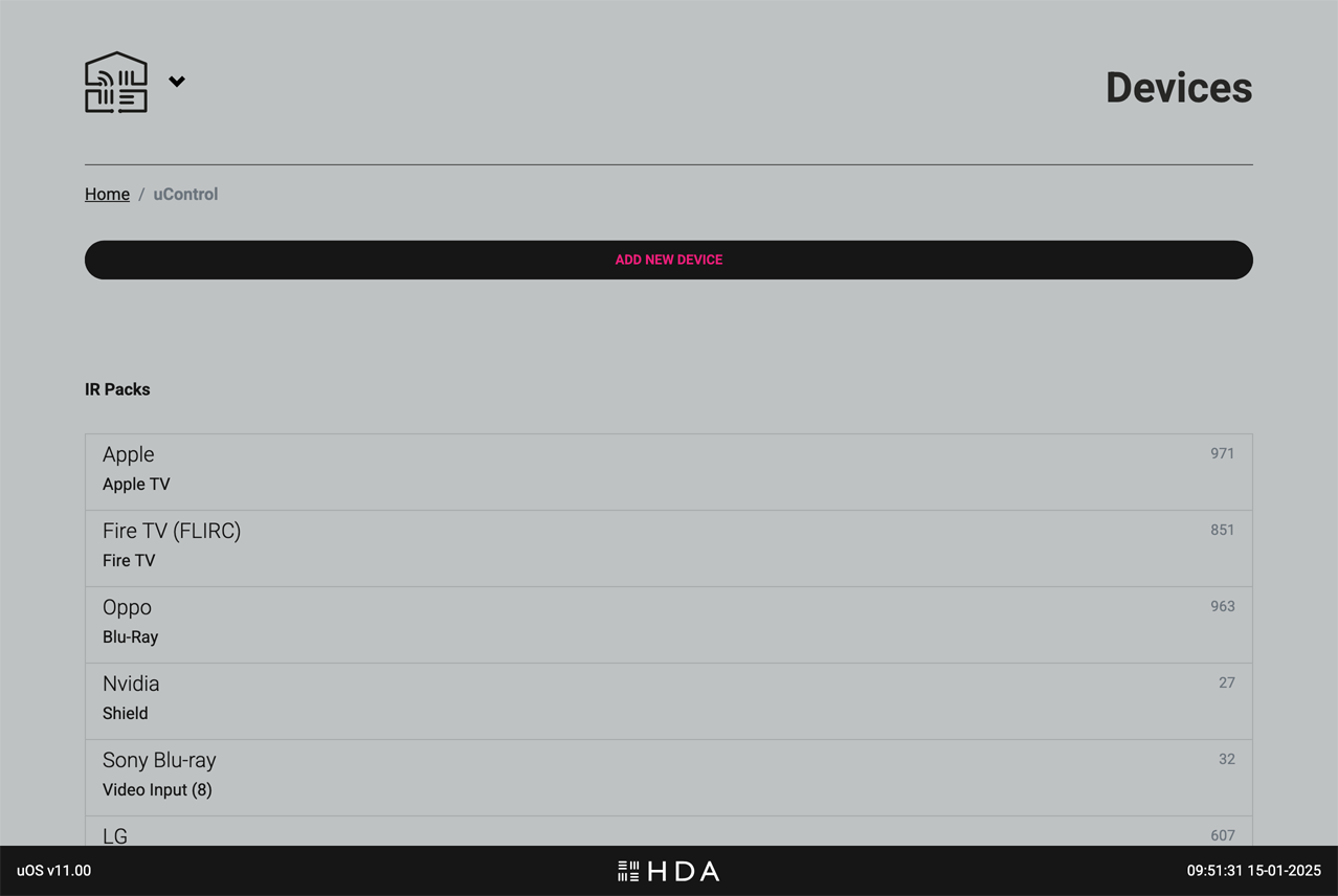
Control your devices and their features seamlessly through the uControl app, a uControl Remote, or Smart Automations. To get started, click or tap on the button labelled “ADD NEW DEVICE” and simply find and install the appropriate uControl pack, driver or establish a uControl IP connection for any Smart Devices (eg, lights, blinds, PDUs etc).
Once installed, all devices that uControl can control will appear here along with any important data such as the current IP address, what input or output the pack is assigned to and the ID.
It is also possible to test CEC commands from the pre-installed uControl CEC pack. This is available at the bottom of the page if your HDA devices supports HDMI-CEC control.
Add device control to uOS
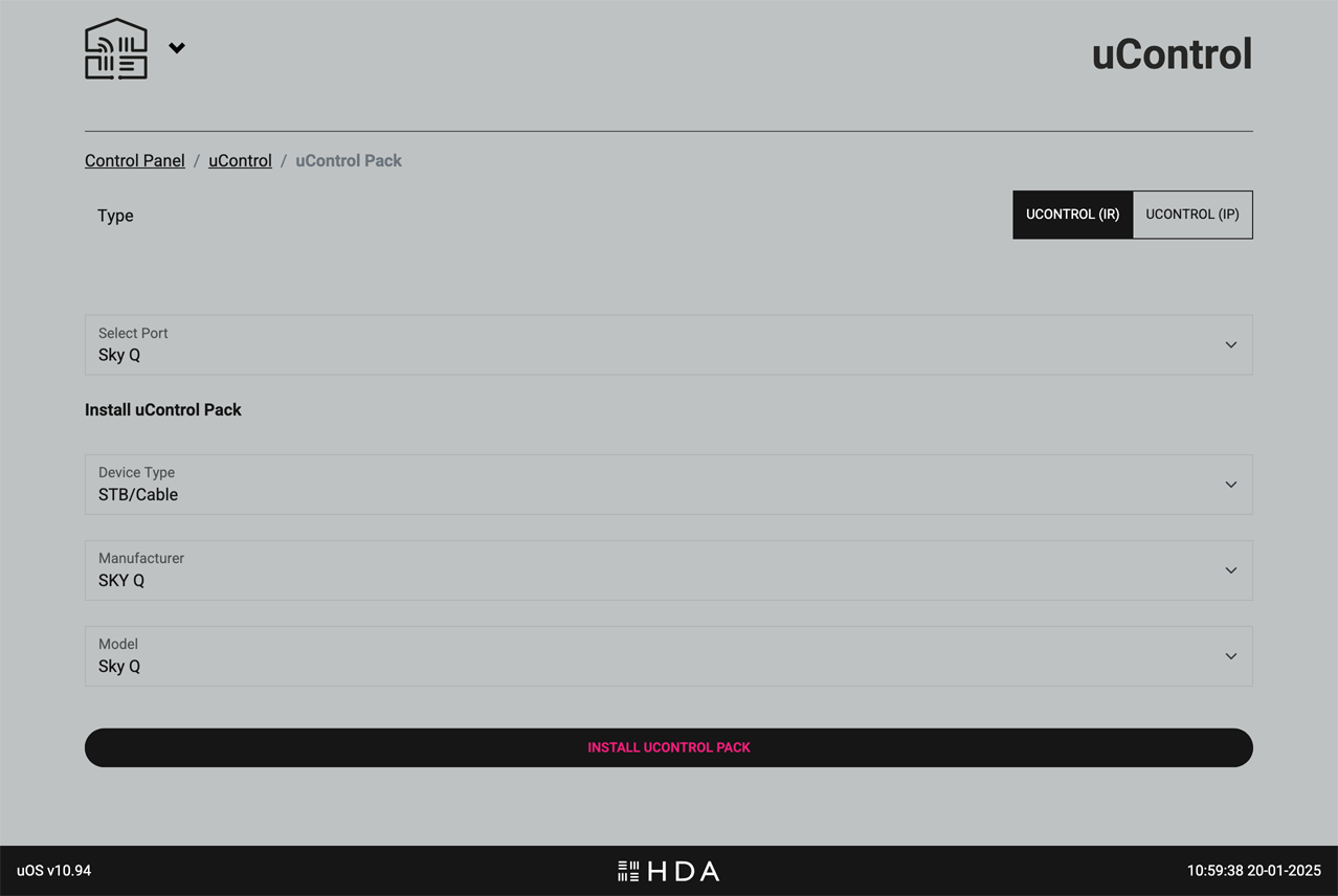
AV Device: select between installing a uControl pack (IR, IP or a Driver) for AV devices like TVs, Blu-ray players, AV receivers, and set-top boxes.

.
Choose between a uControl (IR or IP) pack for the device and select which input or output it is connected to. The AV device might not be connected to an input or output, and can be assigned to a Zone instead.
.
.
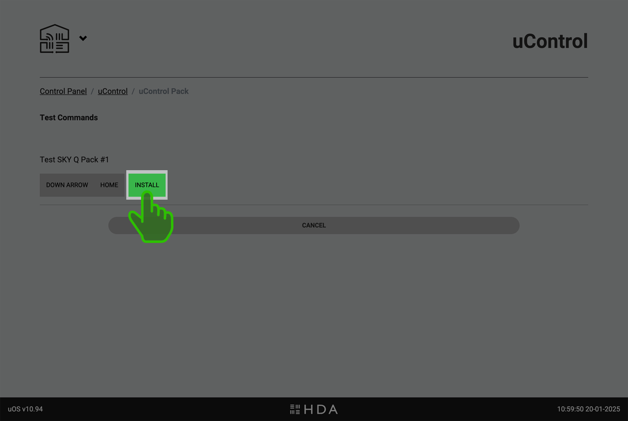
A detailed step-by-step guide can be found here: How to install a uControl pack.
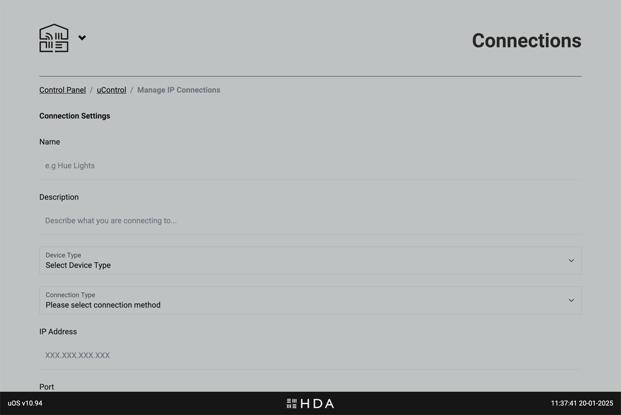
Smart Device: Create a manual IP connection to smart home devices such as smart lighting, blinds/shades, and power sockets/plugs within your Zones.
A detailed step-by-step guide can be found here: Cheatsheets for common Smart Devices.
Smart Automations
Powerful automations to enhance your uControl experience.
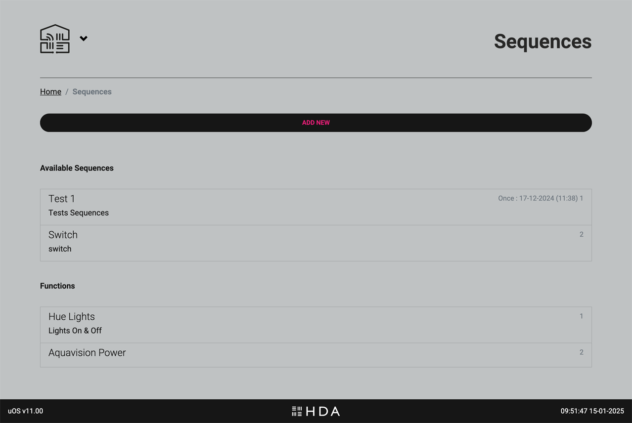
Create powerful automations, called Sequences (a series of commands executed one after another), and add intelligence to them using Functions with “if this, then that” rules to enhance and automate your uControl experience.
You can create Sequences that can turn your HDA device on or off, switch and route inputs or control the volume state in any zone. If you wish to enhance these further with AV device or Smart Device control then ensure you have installed uControl packs for them or have established IP connections before creating your Smart Automations.
Key functions on this page
- Sequences: A sequence is a series of commands executed one after another. For example, a “Movie Night” sequence might dim the lights, lower the blinds, turn on the TV, and start your Blu-ray player.
- Functions: Functions add intelligence to your automations. They can be custom commands or (“if this, then that”) logical rules. For example, a function could automatically adjust the thermostat when the temperature outside changes or turn on the lights when motion is detected.
Scheduling
Automate your Smart Automations with Scheduling
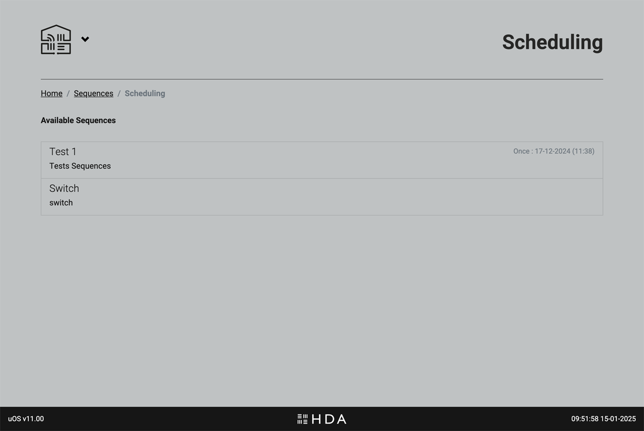
After your Smart Automations have been created you can choose to schedule them to suit your project requirements. For example, you may want all displays in an office environment to turn off at 7pm and for this to happen every Monday to Friday.
Remotes
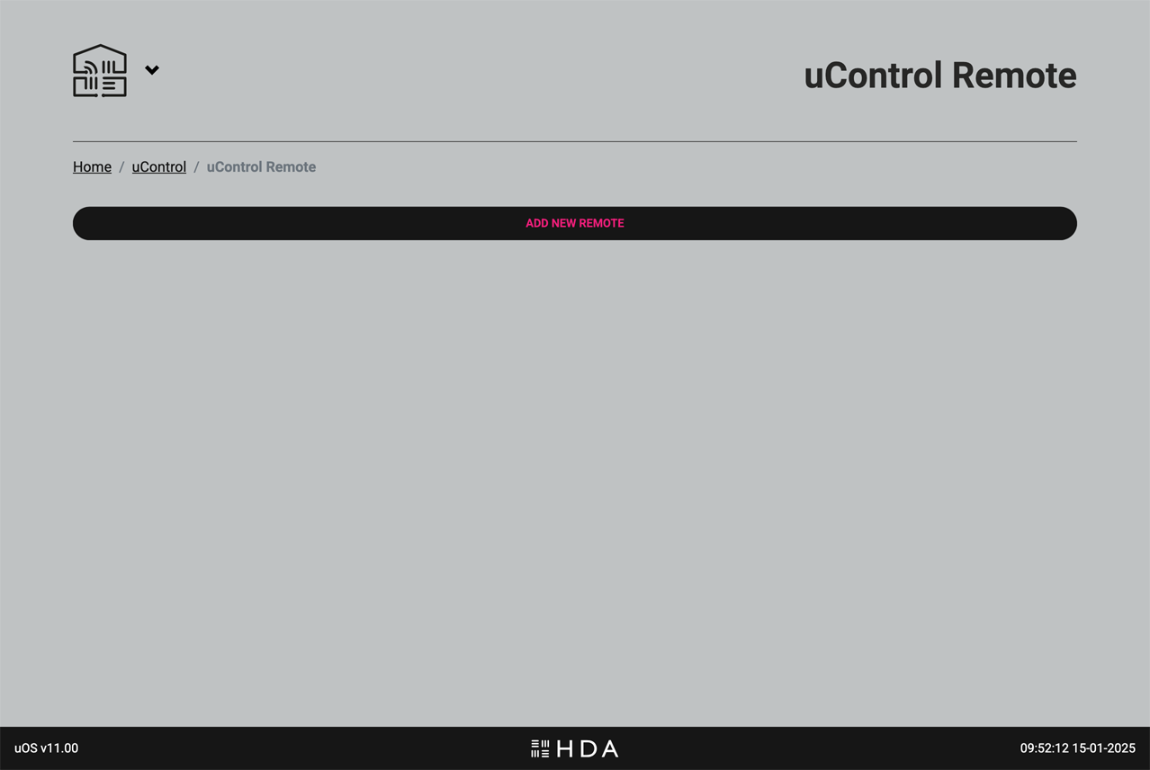
Configure and customise your uControl Remotes.
ADD YOUR REMOTES LAST:
Once you’ve configured your system Zones, installed all packs, set up Smart Automations, and tested everything in the uControl app — it’s time to add your uControl Remote.
Why wait?
This approach streamlines the Remote setup process. By configuring your system first, the settings are automatically copied to the uControl Remote, making the Remote configuration faster and easier. This ensures that your Remote is ready to use with minimal additional setup.
.
Getting the Remote on WiFi & configuring it for use.
A detailed guide on how to configure the uControl Remote can be found here.
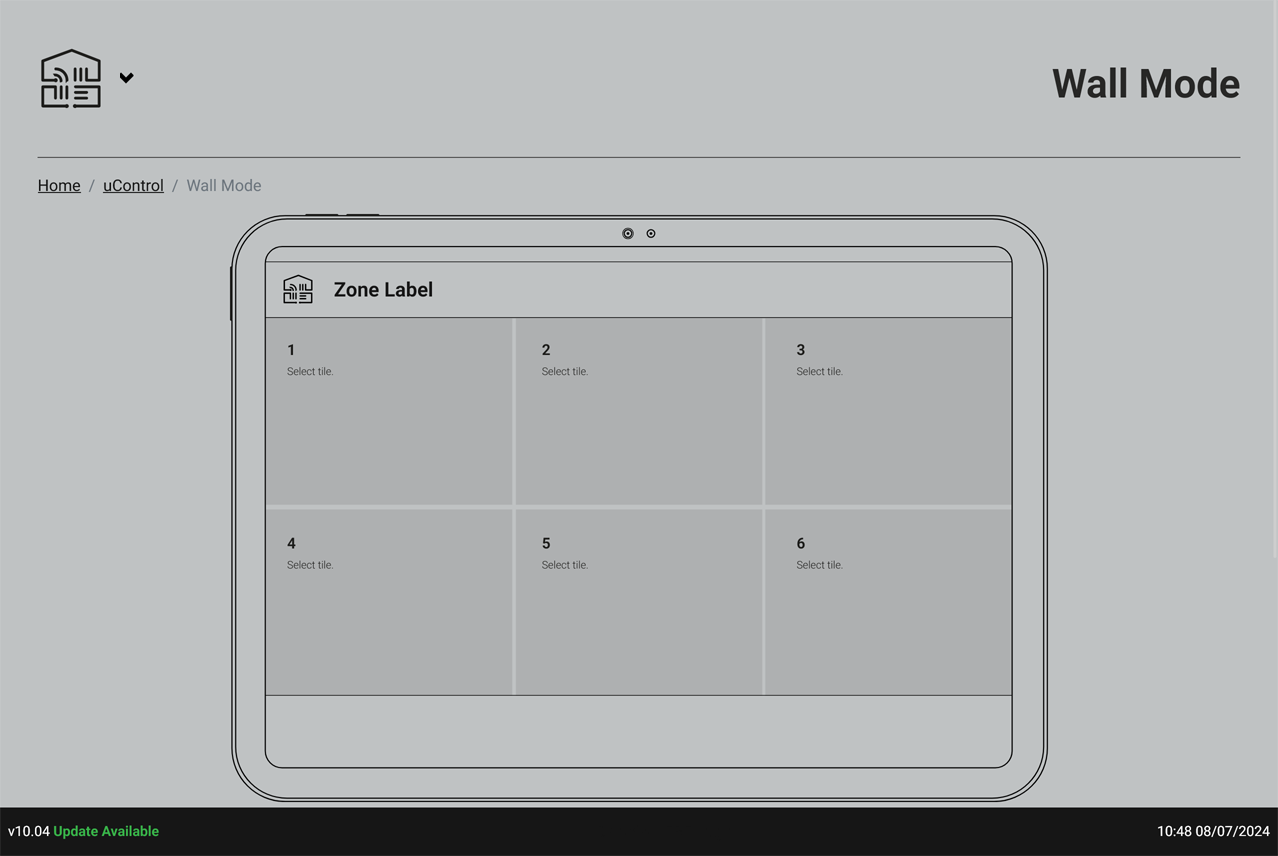
Wall Mode
A simple interface for walls and desktop applications.
.
Design a simplified interface for the uControl app called “Wall Mode.” This mode will display only 6 large tiles on the iPad screen when held in landscape orientation.
Wall Mode is ideal for iPads mounted on walls or placed on tabletops. It makes using the app easier for newcommers or those that do not know how to use the system by hiding all the other menus and options, and presenting the user with just 6 essential controls for a single zone.
IMPORTANT:You can not configure Wall Mode until you have setup Smart Automations. It is recommended that Wall Mode is configured after any uControl Remotes.
To configure a tile, simply click or tap on the tile that you want to configure and add your Smart Automation to it. If uControl driver packs support wall mode configurations then you will have the option to add a driver widget to your tile (e.g Sonos) so that you can see realtime data on that particular tile.
Voice Control
Amazon Alexa voice control
This section allows you to enable or disable Amazon Alexa voice control for your HDA system.
Compatibility
Please note that voice control functionality depends on your specific HDA hardware and system configuration. If your system supports Alexa integration, you’ll find the following options:
A detailed step-by-step guide can be found here: How to configure voice control and account linking to your Amazon Account for the “AV Skill”.
Setup
General uOS setup
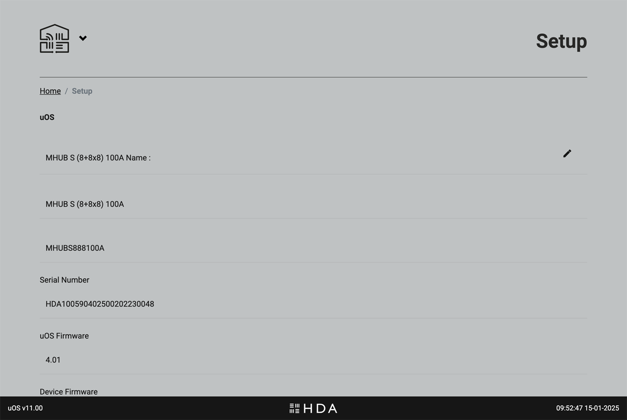
What you will find on this page
- Names and software versions: The official name for your HDA device(s) along with current software and firmware versions.
- Timezone: Set the timezone for uOS. By default, uOS will sync its time to GMT clocks. If you intend on using Scheduling to automate your Smart Automations then it is recommended that you set this to your timezone. This is a manual setting.
- Access control: Set a PIN code to lock access to uOS. It is STRONGLY RECOMMEDED that you keep a record of this PIN somewhere safe or connect your system to HDA Cloud so HDA Support can recover this for you. Once the PIN is set and in the event that it is forgotten or lost, only a system reset will recover your system.
User Accounts
Warranty extension and improved customer service
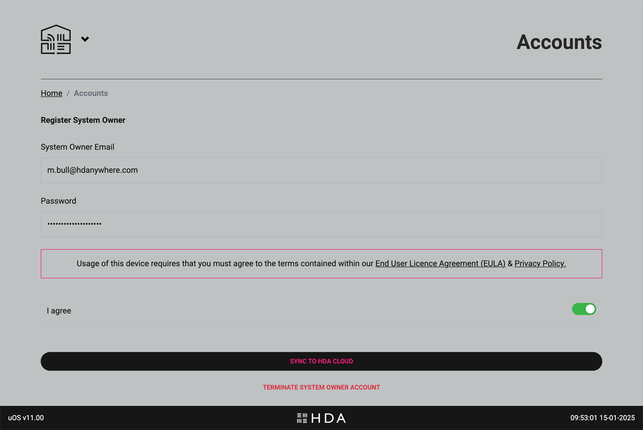
User Accounts connect your HDA device to HDA Cloud, our global data storage and service delivery platform. There are multiple benefits of connecting your HDA device to our cloud servers but the most common reason is the free warranty extension if this is done within 30 days of purchase.
There are two types of account: 1) Owner/User Accounts which belongs to the owner of the HDA device(s) being registered and 2) HDA Pro Accounts which can be used for monitoring the system remotely.
At all times the Owner Account has executive control of uOS, their HDA Cloud account and their HDA device hardware. It is possible to terminate HDA Pro access directly from this page. The absense of an Owner Account will keep the unit technically offline (with the exception of critical updates) and no information about the system or its state will be sent to HDA servers.
Network
Ethernet and WiFi settings for your HDA device(s)
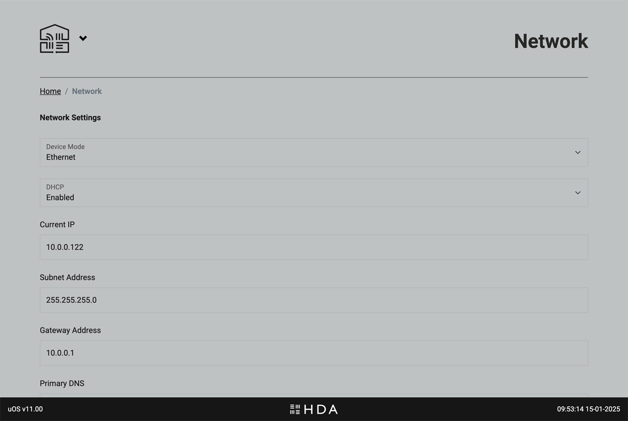
Adjust uOS’ network settings to suit your Local Area Network configuration. IMPORTANT: proceed with care when changing these settings as you can lose connection to your controller if you make a mistake.
Advanced
Power-user access
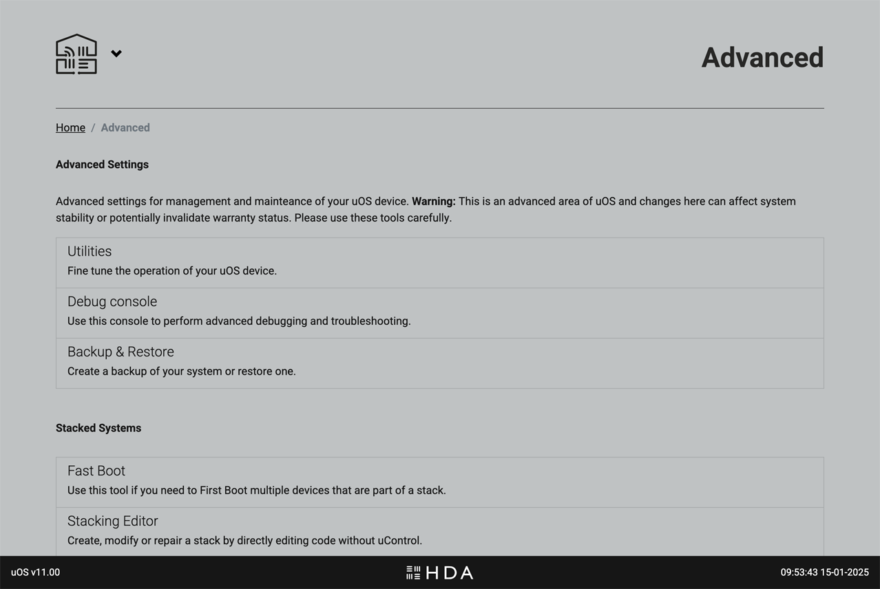
Advanced settings for management and maintenance of uOS. Warning: This is an advanced area of uOS and changes here can affect system stability or potentially invalidate warranty status. Please use these tools carefully.
Before making any changes on this page, ensure you have a thorough understanding of the potential impact. If you are unsure about any settings, please contact HDA support for assistance.
Before you begin:
To ensure a smooth setup process for your uControl Remote, please make sure you have the following in place before you start:
uOS 11 or above: The uControl Remote will work correctly with uOS 11 or above. Ensure that you have checked for updates beforehand.
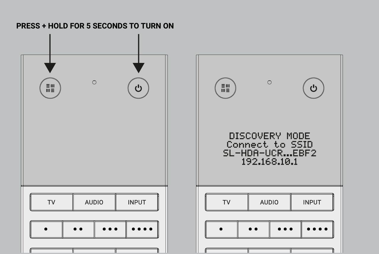
Powered On: Press and hold the HDA Key (top left circular button) and the Power Key (top right circular button) simultaneously for 5 seconds.
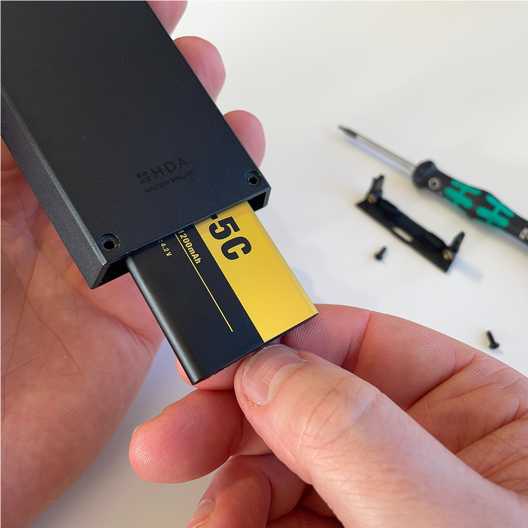
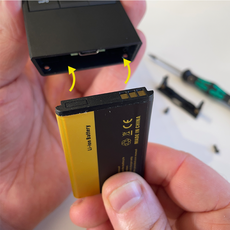
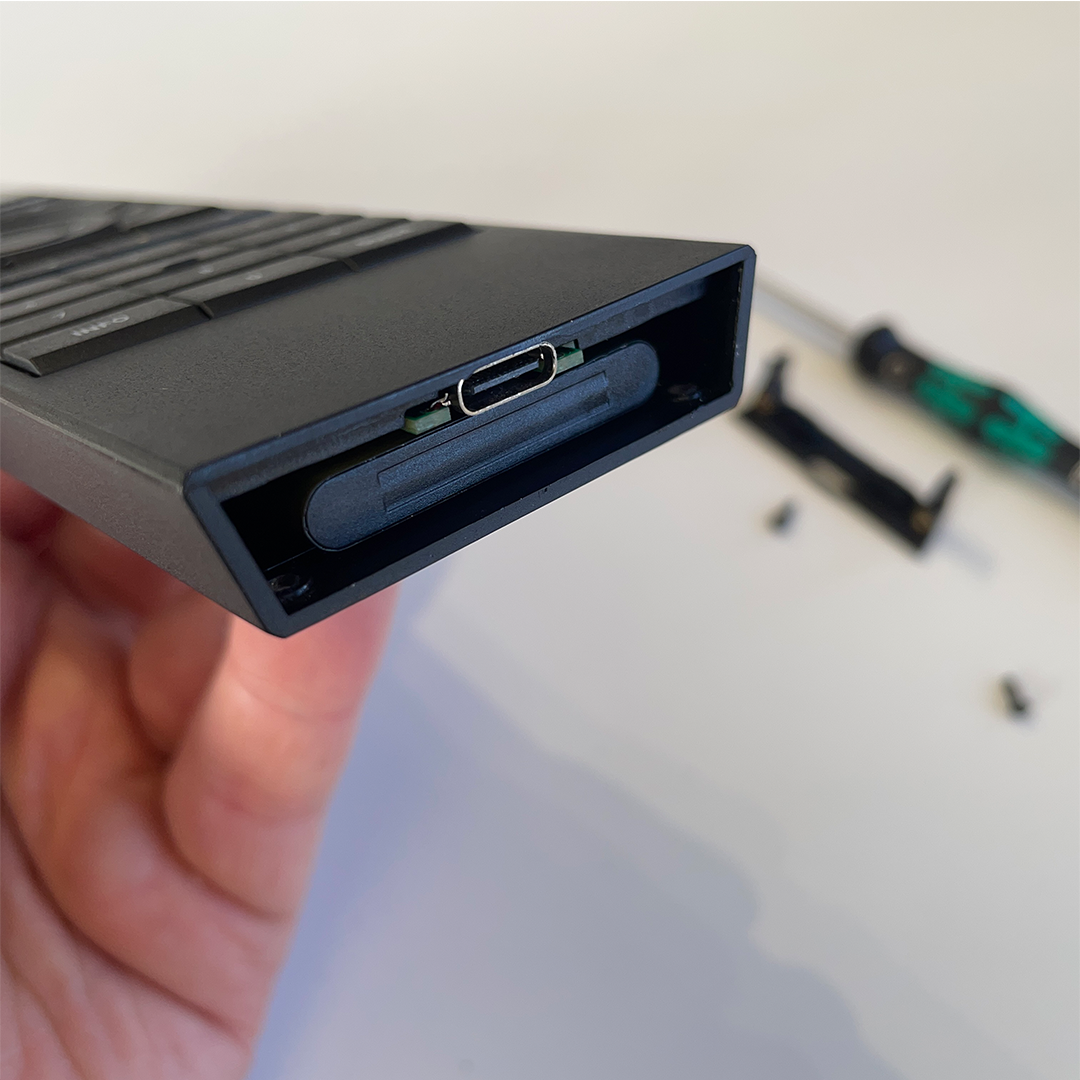
Sufficient Power: Ensure the Remote is charging using the provided USB-C cable or a wireless charger.
Setup tested on uControl app: uControl Remote should be the last device setup in uOS. It is recommended that all uControl packs have been downloaded, all Smart Automations have been created and tested inside uControl app before transfering any configuration to .
20 minutes (approximately) to work through.
Contents:
In a hurry? Refer to the quick start guide in your packaging
The fastest way to connect your uControl Remote to your WiFi network is to refer to the quick start guide found inside your packaging.
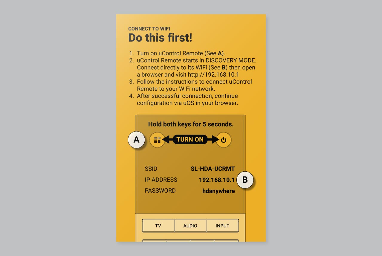
If you need more help then a detailed version of this process is described below.
Getting uControl Remote on your WiFi network (full description)
1. Ensure that the uControl Remote is charging before you start
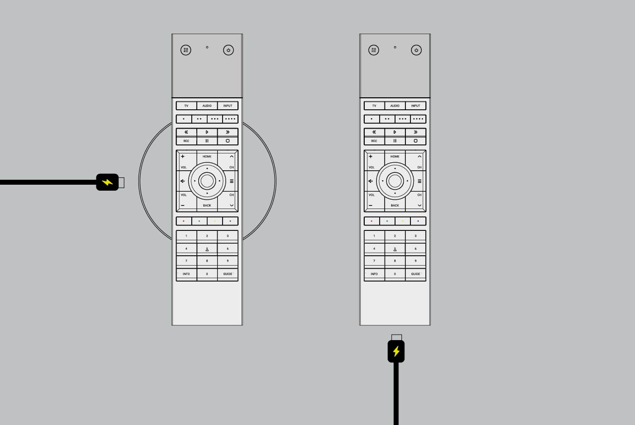
2. Turn the uControl Remote ON
3.Connect directly to uControl Remote’s WiFi
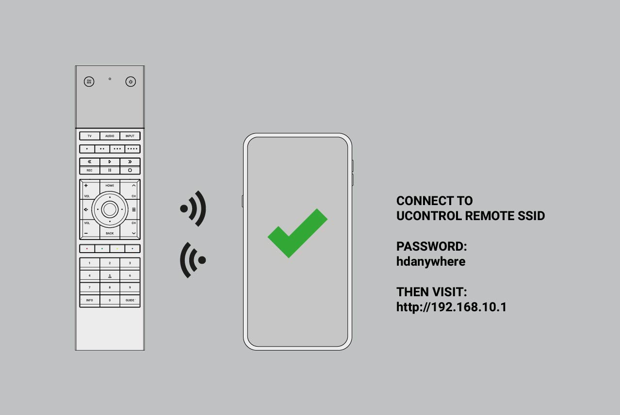
To connect to uControl Remote’s WiFi use password hdanywhere.
4. Access the uControl Remote’s Network Page.
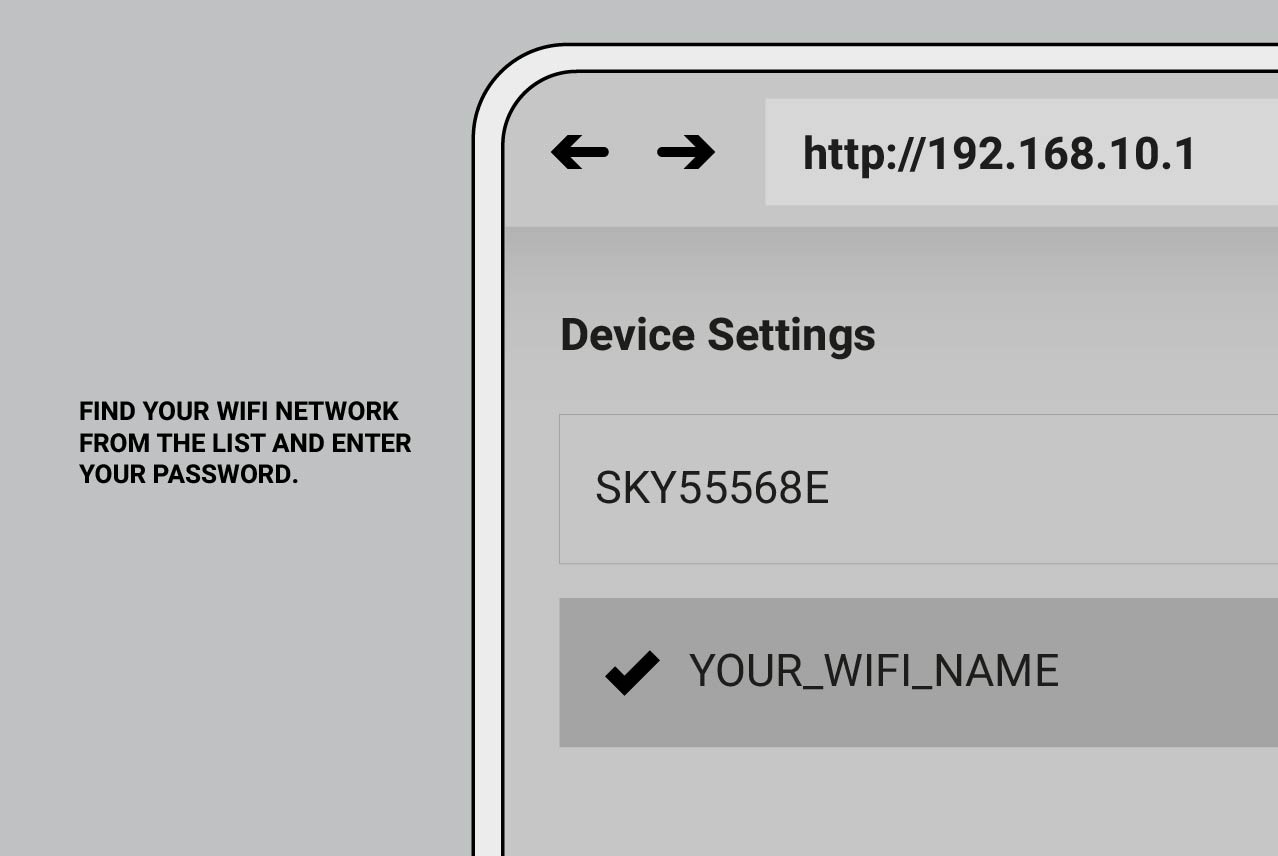
At this stage, uControl Remote will scan all available WiFi networks within range. uControl Remote only supports 2.4GHz WiFi and WPA/WPA2/WEP security standards.
5. Wait for connection
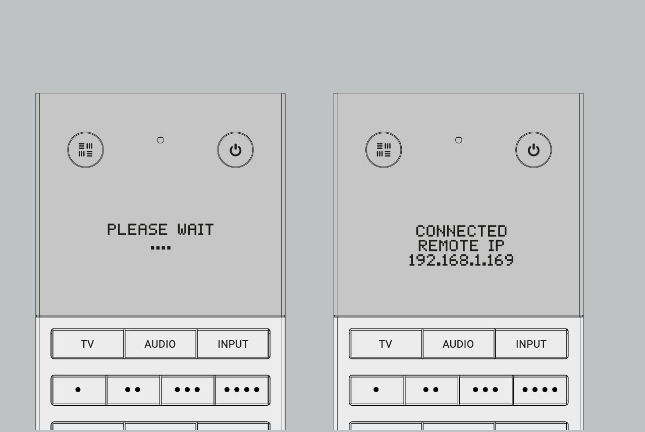
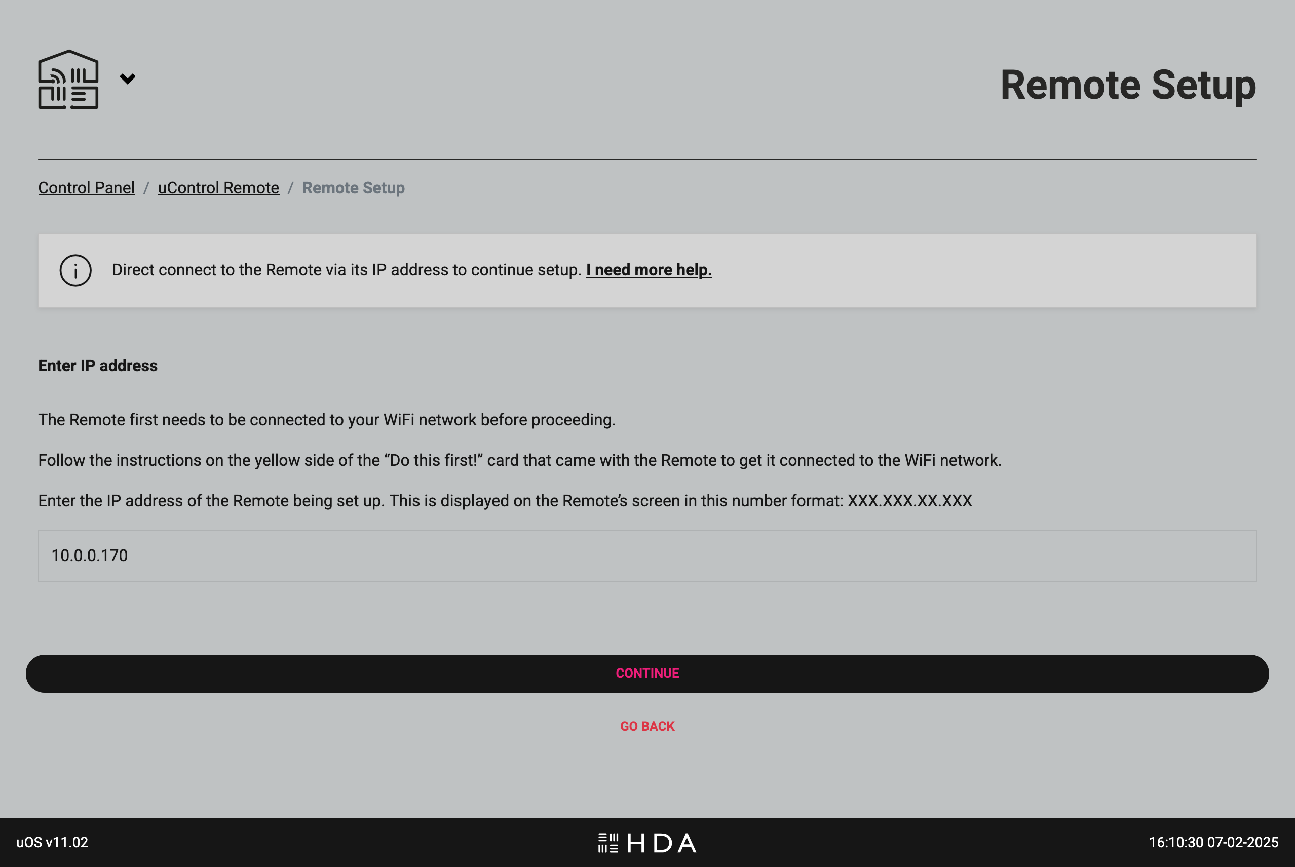
Once the uControl Remote has joined your WiFi network, it will be given a new IP address, take a note of this IP address as you will need it when you configure your uControl Remote for use.
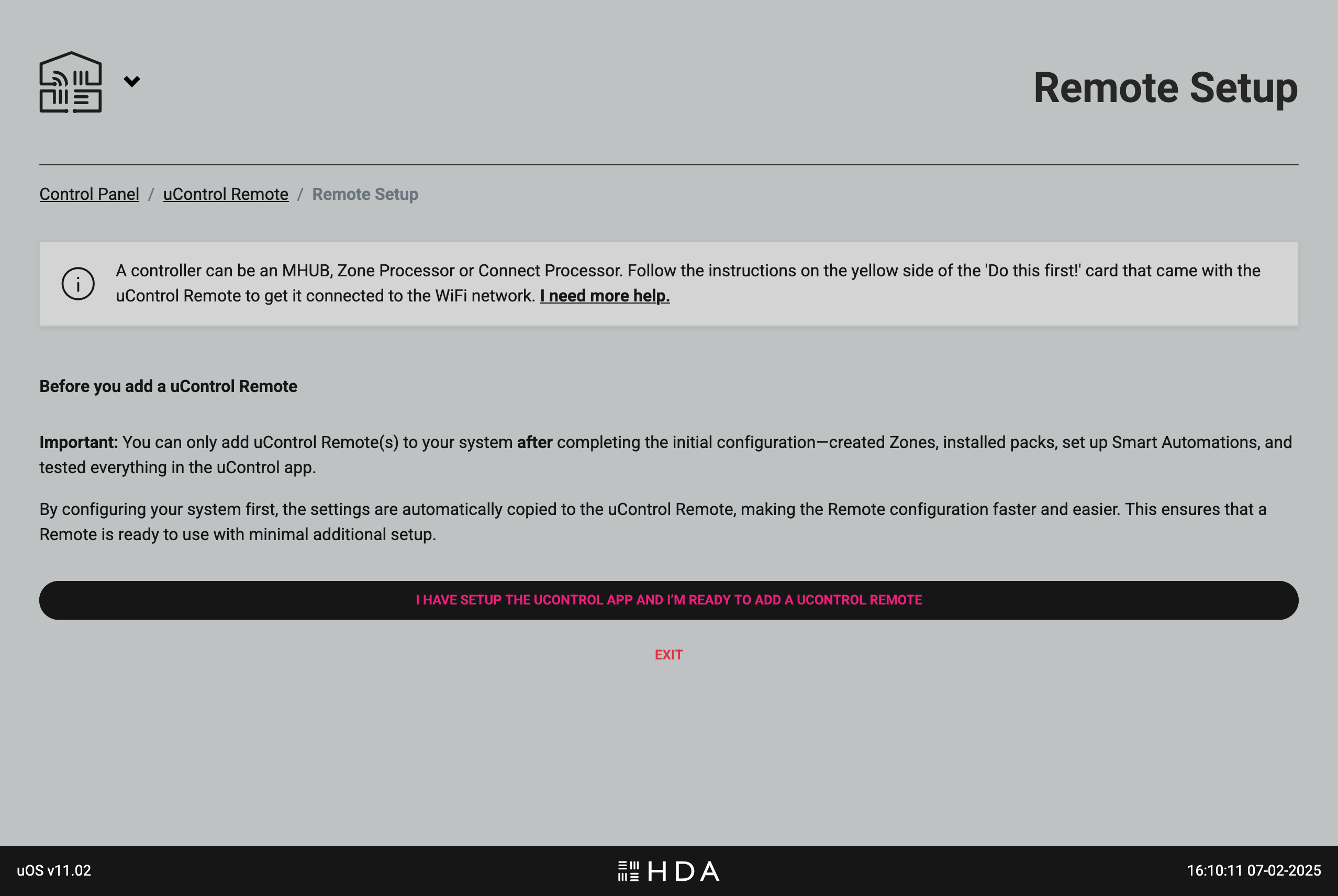
Starting uControl Remote basic configuration.
Make sure your uControl Remote is on the same network as you controller and that the Remote is charging.
Visit uOS and navigate to the “Remote” page.

Make sure that all uControl Packs, Smart Automations & Zone Settings have been completed before proceeding.
Enter your uControl Remote’s IP address.
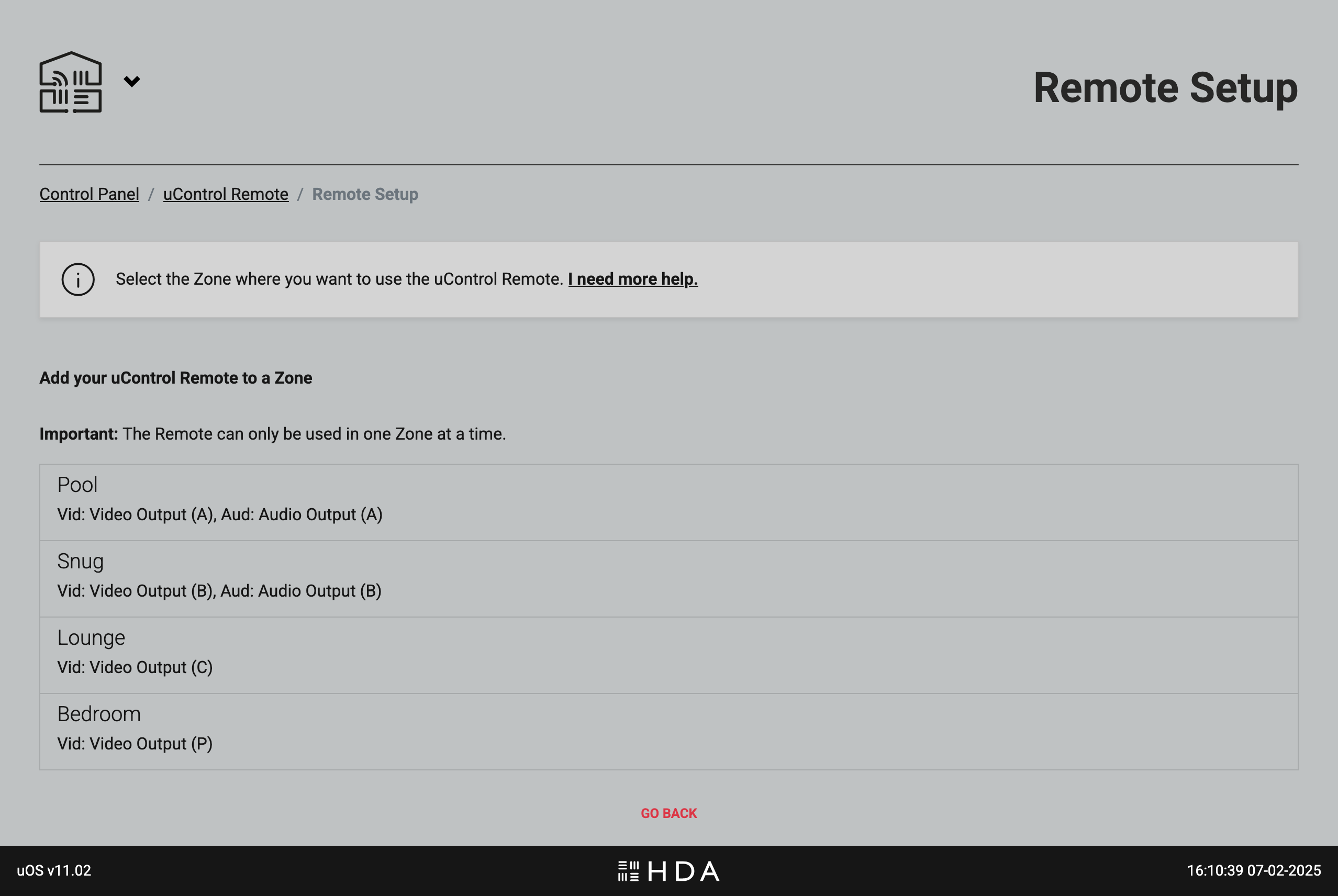
Add your uControl Remote to your Zone or Room.
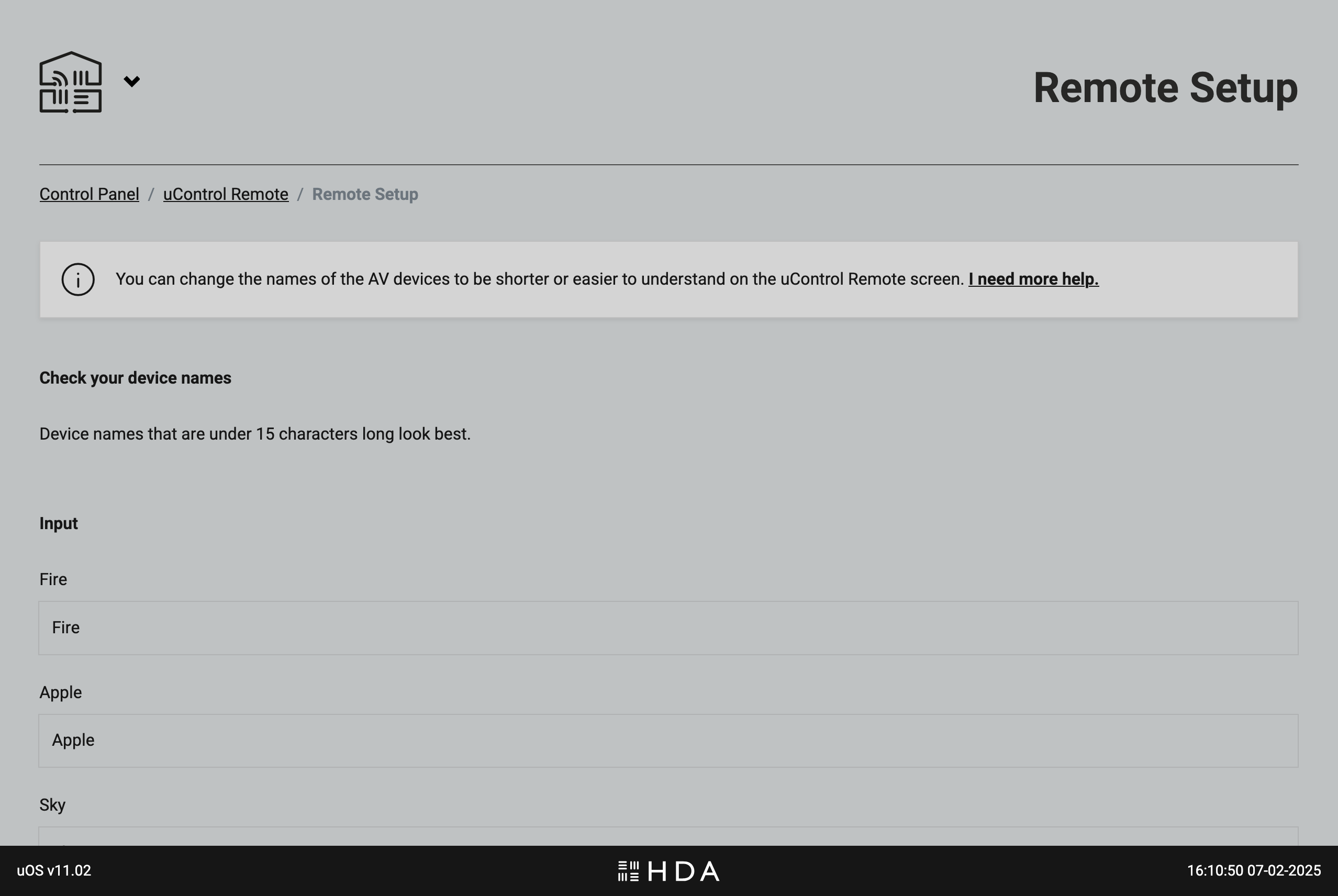
Optional step: rename your devices so they are easier to read on uControl Remote’s screen.
Select what will be doing the volume control in your Zone or Room.
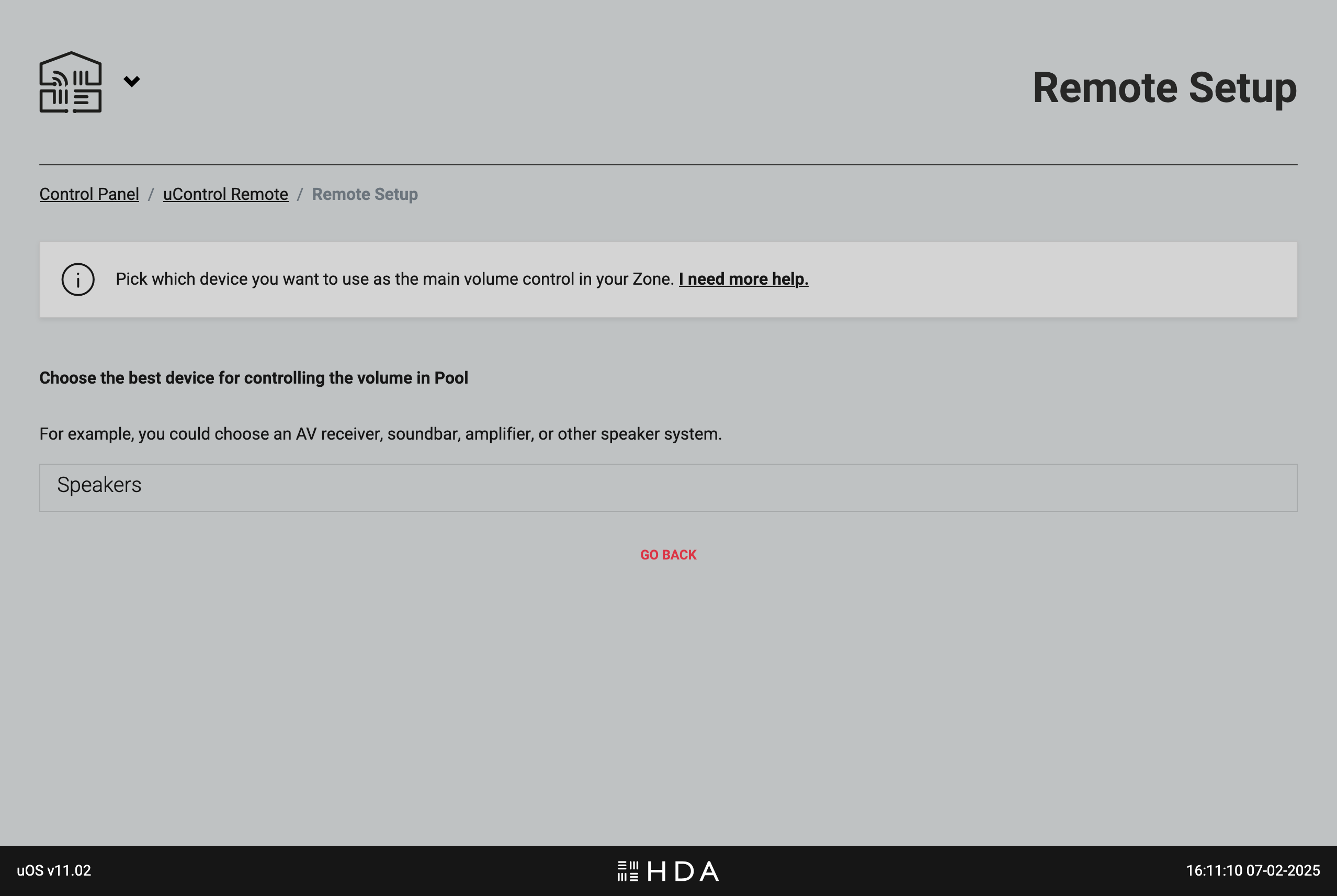
More about volume: uOS will automatically select devices you’ve installed that offer volume control and will present them in this list based on how they are categorised by HDA. This includes TVs, Projectors, audio streamers/amplifiers (Wiim, Sonos), AVRs and HDA hardware like MHUB or MZMA.
If you have multiple devices that are all volume controllable (eg TV + AVR) then you will still need to nominate which device is default but uOS will transfer all options to the remote. This means you can switch away from the default option by pressing and holding the “AUDIO” key on the Remote. If you power down the remote or it is restarted, uControl Remote will revert to it’s default setting.
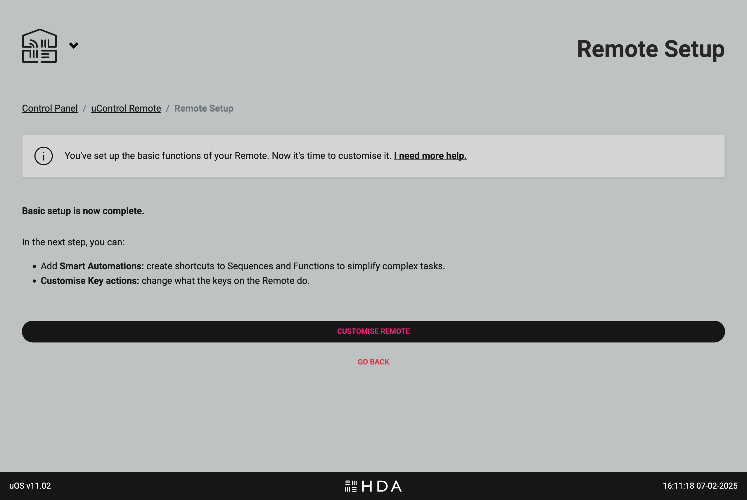
Basic setup is complete.
Included below are some troubleshooting steps we recommend carrying out if having issues with integrating Control4 with HDA devices:
Unable to connect your MHUB to the driver?
- There are many drivers to choose from so you must ensure you have the correct one installed, a link to our drivers page can be found here. There are drivers for basic switching or product specific drivers that offer a more in dpeth form of control, so it is vital the correct one is downloaded and that you are not using an old copy. If you are unsure which driver to download please contact support.
- Ensure that your HDA device has not changed its IP address.
- Try manually connecting to the system by inputting the HDA devices IP address into the driver, making sure to disable auto-discovery.
- Make sure that the devices are up to date.
- Go through first boot on MHUB-OS or uOS.
- Make sure you have set the unit to be powered on at all times in the driver by setting the state to true.
Connected but having issues controlling the system?
- In a Stacked System you will need to download a separate instance of the driver for each unit.
- Make sure the correct ports are assigned in the driver.
- If you’re using IR pass-through make sure to use our IR Transmitters.
Picture problems can occur in an MHUB Stacked System when there is a laptop or PC as an input. The problem presenting itself can vary depending on the graphics card in the device and typically picture passes to the first MHUB in the Stack (S1), but not to the second MHUB (S2).
To resolve the issue we can place an HDMI Splitter MAX (1×2) in between the input (laptop/PC) and the Source (IN) port on MHUB. Your laptop or PC woud be connected via HDMI and plugged into the unlabelled input on the HDMI Splitter MAX (1×2), then taking another HDMI cable plug this into the HDMI port labelled A on the splitter and connect it into your desired input on the Foundation Layer (S1). For the second MHUB (S2) you would take another HDMI cable and plug it into the port labelled B on the Splitter, and connect it to the Source (IN) port on the second MHUB (S2).
If you are part of one of the unlucky 2% this issue affects please note that this is the most efficient work around to date, however, we are investigating a more permanent software fix for a future rollout. If this work around fails and the issue persists, which can happen please contact HDANYWHERE Support.
Wiring diagram:
Philips Hue Sync boxes can add a layer of depth to your home cinema experience, however, it can cause problems to a system as adding this switch at the display end can interfere with EDID and HDCP signals causing picture/audio problems.
While this issue does not always happen with a Philips Hue Sync box in an A/V distribution system, when it does there is a setting that can be disabled to work around it which is CEC.
There is an article on disabling CEC for your HDANYWHERE system which covers sending the command via a URL/web browser search bar, Hercules and Netcat. If you disable CEC and are still having issues with your Philips Hue Sync box please contact HDANYWHERE Support.
You may not need to use CEC or you have been prompted to disable it by support as it can cause conflicts between displays and external devices like soundbars, causing audio pass-through issues.
The examples in the guide focus on disabling CEC, however, to re-enable it replace “Off” with “On”.
There are 3 ways to disable CEC:
Please note
The command variable is x meaning you put the Output port here when you want to disable it. To disable Output A put 1, to disable Output B put 2 and so on. To disable all Output ports +1 to however many HDBaseT ports there are. For example if you have a 4-way matrix input 5 to disable all ports.
Using an MHUB S (8+8×8)? Make sure to only send HDMI command – CecOutxOff!
URL
To execute the command successfully you will need to be on a laptop/PC which is connected to the same network as your HDA device, and its IP address. For this example our HDA devices IP address is 192.168.0.149. Send it in your web browsers URL/search bar, the first command disables CEC for HDMI and the second command is for HDBaseT.
HDMI
HDBaseT
If done correctly you will see a response saying “Cec Out x Off” for one Output that has been disabled or “Cec Out all Off” if all Outputs were disabled.
Hercules
![]() Hercules SETUP utility
Hercules SETUP utility
useful serial port terminal (RS-485 or RS-232terminal) , UDP/IP terminal and TCP/IP Client Server terminal. Produced by www.HW-group.com.
If you don’t have Hercules already download it using the link above, we can use it to send our CEC command to our device. Once installed run the software. Hercules only requires the command itself so you don’t need to include 192.168.0.149/api/instr?cmd= like you do in URL.
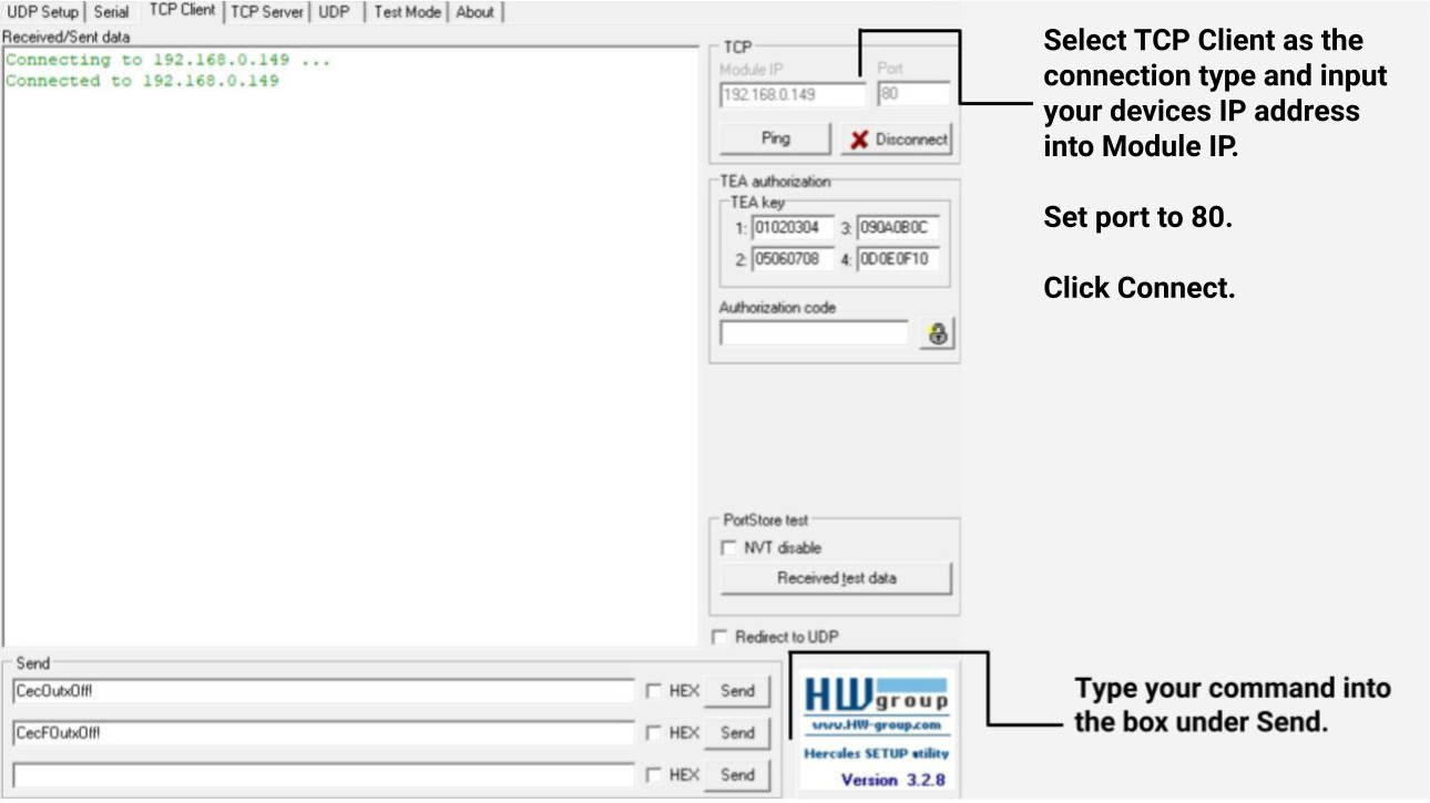
You should see a response in black below Received/Sent data saying CEC has been disabled if done correctly.
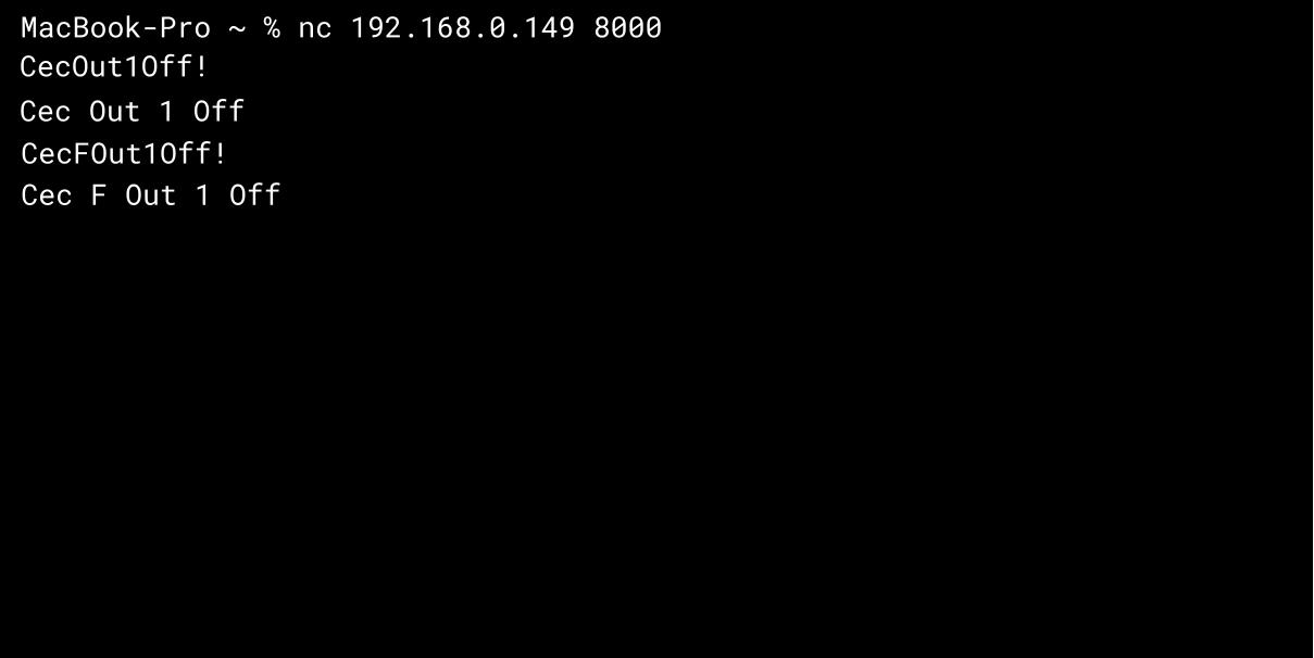
Nc
Netcat can be used to send direct commands to a device via TCP or UDP. You will need to open up your terminal and enter nc 192.168.0.149 8000 and press enter.
Please note 192.168.0.149 is only an example IP address and yours may be different. Below you will see both the HDMI command (CecOut1Off!) and HDBaseT command (CecFOut1Off!) being sent with their responses below, to exit press Ctrl + C.
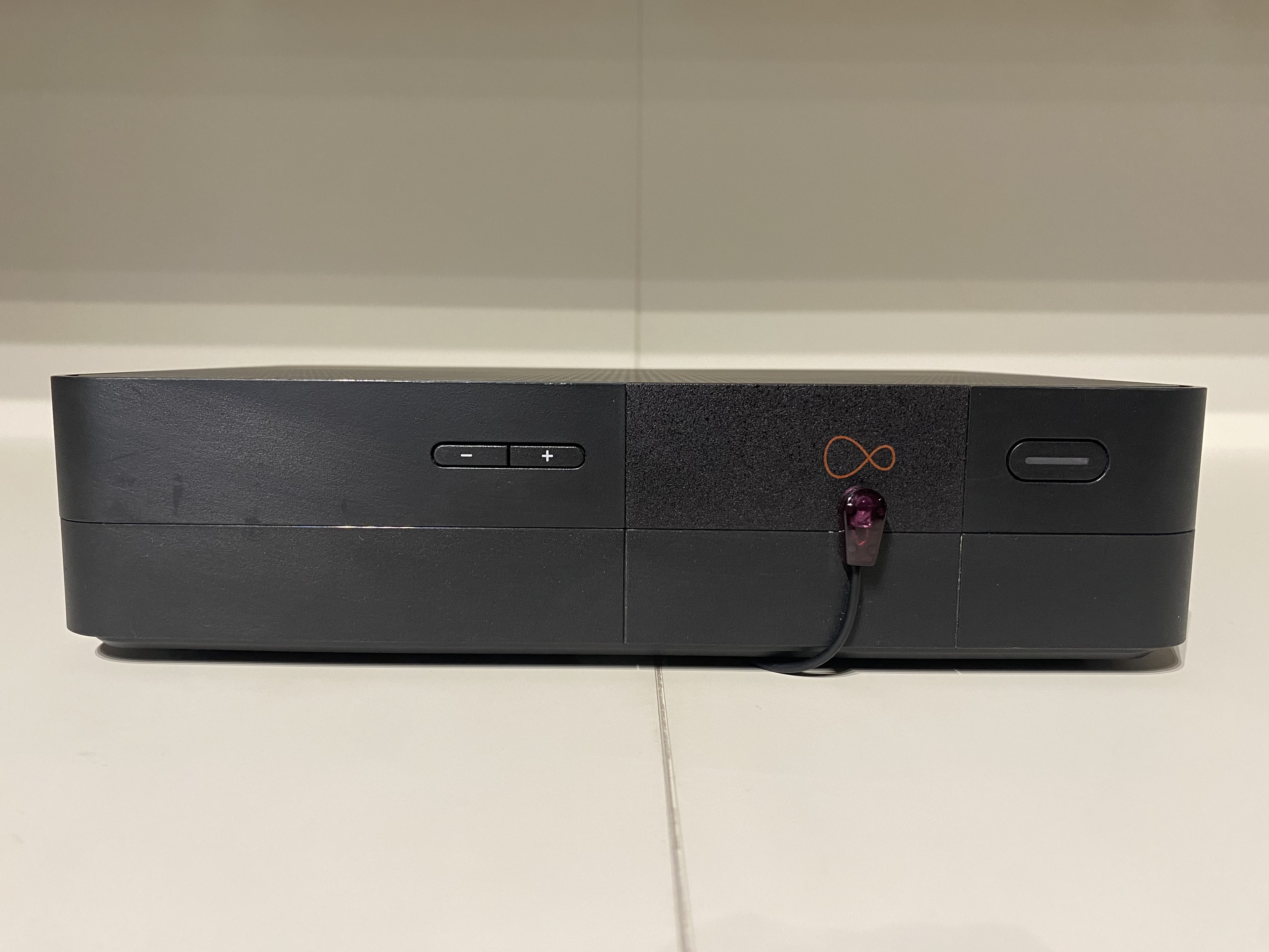
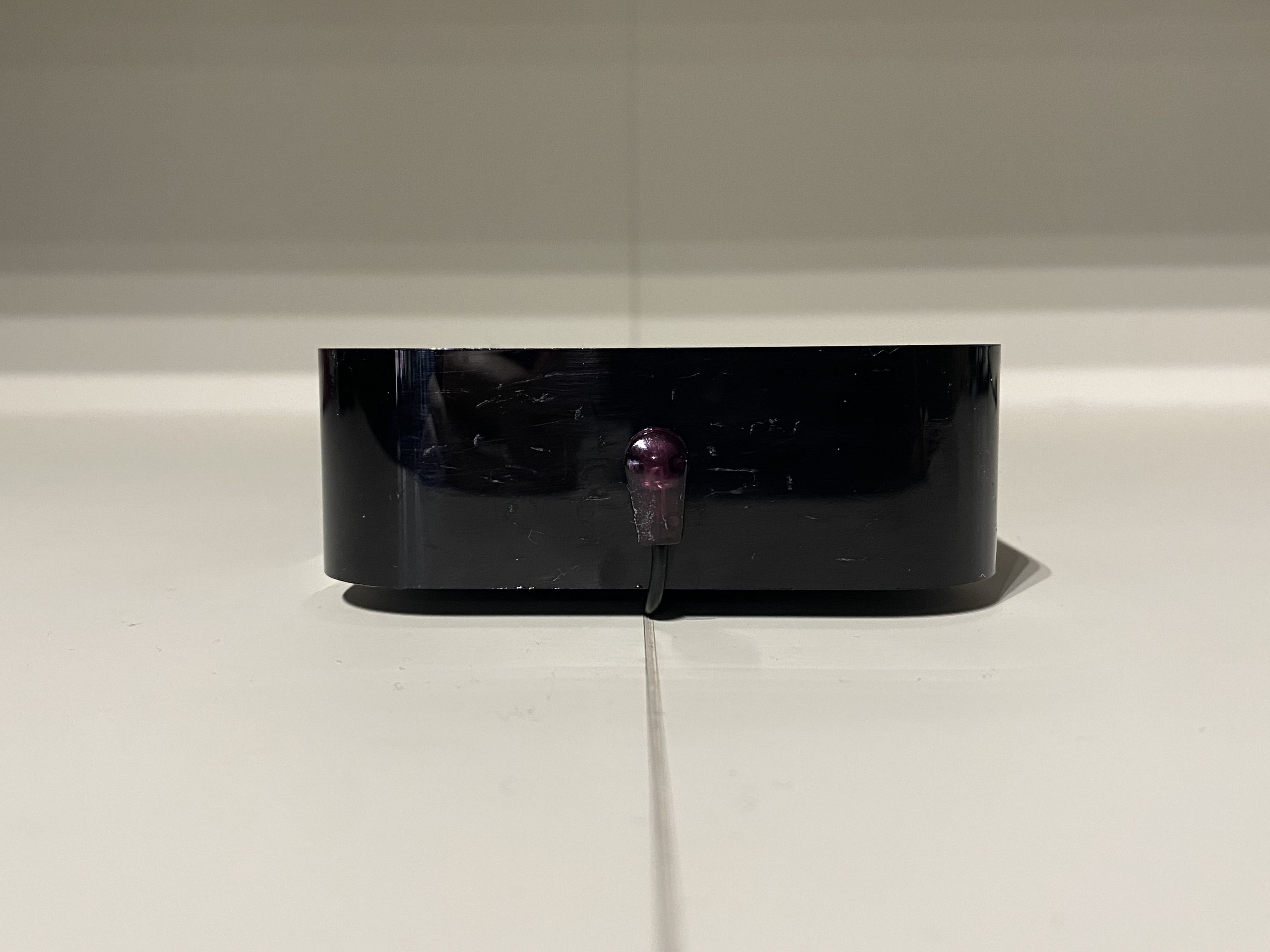
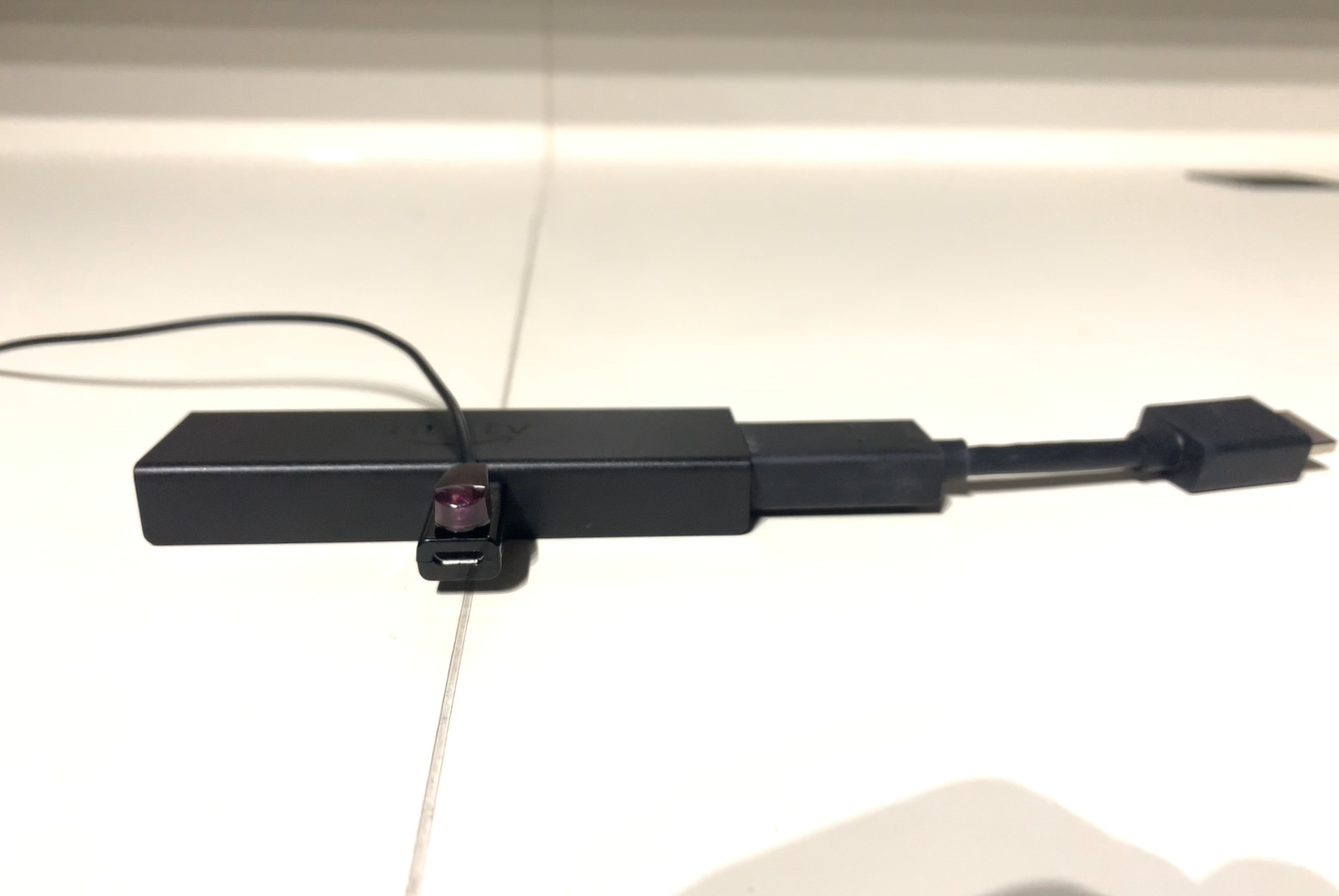
Some source devices need the IR transmitter to be placed in a very specific location. This page shows a number of popular controllable soure devices and their IR transmitter positioning incase you’re unable to locate it.
Sources:


![]()


HDANYWHERE will be operating a reduced customer and dispatch service over Christmas and New Year. Dispatch will resume in the new year and the last day for dispatch is Thursday 21st. During this period a reduced customer service level will operate meaning Call Back Requests and WhatsApp messages will be temporarily disabled until January 2nd.
- Thursday 21st December 2023: Last day of dispatch
- Friday 22nd December 2023: No dispatch. Reduced customer service.
- Wednesday 27th December 2023: No dispatch. Reduced customer service.
- Thursday 28th December 2023: No dispatch. Reduced customer service.
- Friday 29th December 2023: No dispatch. Reduced customer service.
- Tuesday 2nd January 2024: Dispatch resumes. Full customer service.